Punjabi Mughal
Newbie level 4
i want to use instead of 2sk3299
Follow along with the video below to see how to install our site as a web app on your home screen.
Note: This feature may not be available in some browsers.
 the only mcu available here are attiny13 and mega8 dip version.
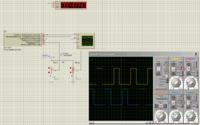
 because this is slightly simple decision.why signal generate
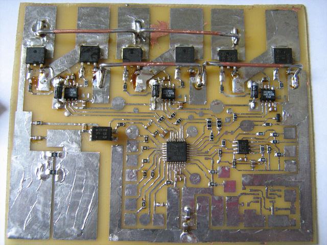
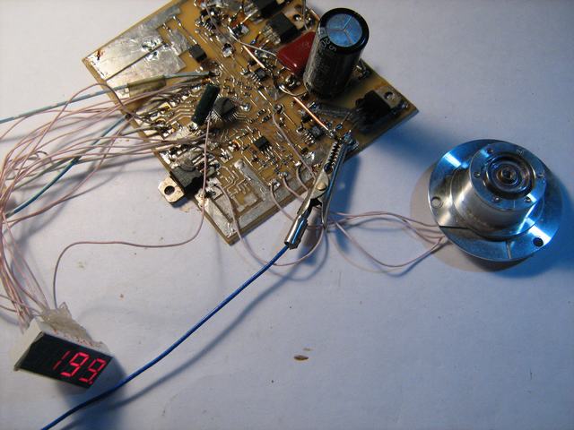
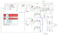
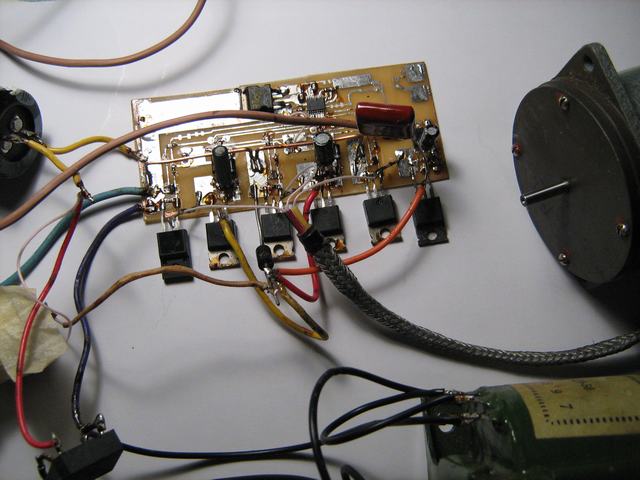
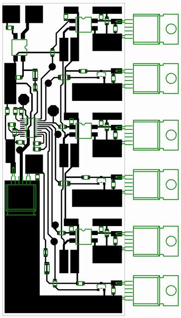
DCDC_12_350 based on ATTiny13 project