Continue to Site

Welcome to EDAboard.com

Welcome to our site! EDAboard.com is an international Electronics Discussion Forum focused on EDA software, circuits, schematics, books, theory, papers, asic, pld, 8051, DSP, Network, RF, Analog Design, PCB, Service Manuals... and a whole lot more! To participate you need to register. Registration is free. Click here to register now.

Simulating 433Mhz Dipolo with ADS

Status
Not open for further replies.

tomars

Junior Member level 2
Joined
May 25, 2022
Messages
23
Helped
1
Reputation
2
Reaction score
0
Trophy points
1
Activity points
128
I need help for this.

I made two simulation, using one pin and grond, and one +pin and one - pin
Result is more different.
What is the right method ?
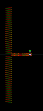
Using one pole and Grond, i see little activity on bottom pole, on momentum Visualization, animation.

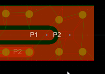
P1 P2 are +/- pole
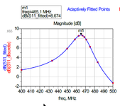
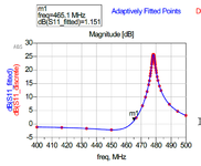
sim2 is P1 + GND
sim2_2 is P1+ P2-
 

Attachments

  • Dipolo.png
    Dipolo.png
    44 KB · Views: 120
  • Pin.png
    Pin.png
    34.9 KB · Views: 109
  • sim2.pdf.png
    sim2.pdf.png
    42.2 KB · Views: 121
  • sim2_2.pdf.png
    sim2_2.pdf.png
    43.5 KB · Views: 121

The difference between cconcrete to 0mm, and 1mm from the PCB is really a lot.
It is a really too unstable situation.
Maybe is better if i make antenna on a single layer, opposite to concrete.

On test:
PMMA + copper + fr4 + copper + fr4 + air + concrete
Changing air thickness, it seems that it is less unstable.
 

Status
Not open for further replies.

Part and Inventory Search

Welcome to EDABoard.com

Sponsor

Back
Top