tomars
Junior Member level 2
I need help for this.
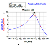
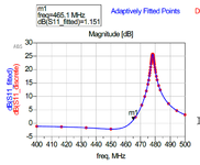
I made two simulation, using one pin and grond, and one +pin and one - pin
Result is more different.
What is the right method ?
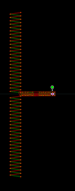
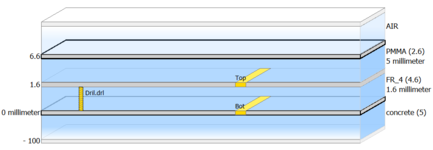
Using one pole and Grond, i see little activity on bottom pole, on momentum Visualization, animation.
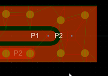
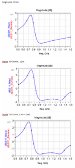
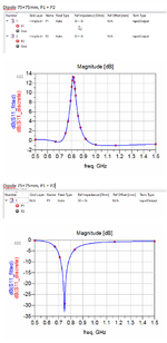
P1 P2 are +/- pole
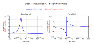
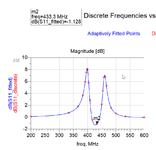
sim2 is P1 + GND
sim2_2 is P1+ P2-
I made two simulation, using one pin and grond, and one +pin and one - pin
Result is more different.
What is the right method ?
Using one pole and Grond, i see little activity on bottom pole, on momentum Visualization, animation.
P1 P2 are +/- pole
sim2 is P1 + GND
sim2_2 is P1+ P2-