Continue to Site

Welcome to EDAboard.com

Welcome to our site! EDAboard.com is an international Electronics Discussion Forum focused on EDA software, circuits, schematics, books, theory, papers, asic, pld, 8051, DSP, Network, RF, Analog Design, PCB, Service Manuals... and a whole lot more! To participate you need to register. Registration is free. Click here to register now.

Simplest Mixer configuration

Status
Not open for further replies.

shabazsyed

Junior Member level 3
Joined
Dec 28, 2011
Messages
25
Helped
1
Reputation
2
Reaction score
1
Trophy points
1,283
Activity points
1,466
Capture.PNG
HI GUYS ,
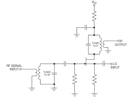
I read from RF razavi book that above shown config can be used has mixer. Can anyone help me out in designing and verifying it.Will post the results once done. IT should be in Linear region to multiple RF and Lo. For this i bias RF lower Compared to LO. Now how do i calculate the gain Equation for it. Thanx
 

Any non-linear element like a diode or a transistor can be used as a mixer. You feed a LO power to it to make it switching, then another signal to input creates linear combinations, one of which you select as desired, and filter out the others.
For your (Razavi's) FET structure, the rules are the same. You need to set a DC bias so the response is not linear. Such mixer may have a conversion gain but expect rather a loss.
 

As your circuit has no DC supply, the mosfet will act as a switch that will go on and off in the rythm of the LO signal applied to the gate.

This functions as a mixer, as it is like multiplying the input signal with square wave with amplitude =1 (assuming sufficient LO drive). The conversion loss is greatly affected by the behavior of ZRF and ZIF for out of band frequencies.

Note that this type of mixer also reflects the difference and sum frequenties back to the input (so it reradiates more that the LO signal alone).
 

You need to set a DC bias so the response is not linear. Such mixer may have a conversion gain but expect rather a loss.

If i bias the mos in linear region, How is the response not linear. And in linear region i have kp(Vlo-vt)*Vrf right , then my conversion gain should be RL*kp*(Vlo-vt). is it right.? I didnt understand how u said conversion loss. Thank you for replying jiripolivka :)

---------- Post added at 08:35 ---------- Previous post was at 08:34 ----------

If i bias the mos in linear region, How is the response not linear. And in linear region i have kp(Vlo-vt)*Vrf right , then my conversion gain should be RL*kp*(Vlo-vt). is it right.? I didnt understand how u said conversion loss. Thank you for replying jiripolivka :)

---------- Post added at 09:24 ---------- Previous post was at 08:35 ----------

As your circuit has no DC supply, the mosfet will act as a switch that will go on and off in the rythm of the LO signal applied to the gate.

This functions as a mixer, as it is like multiplying the input signal with square wave with amplitude =1 (assuming sufficient LO drive). The conversion loss is greatly affected by the behavior of ZRF and ZIF for out of band frequencies.

Note that this type of mixer also reflects the difference and sum frequenties back to the input (so it reradiates more that the LO signal alone).

Thanks WimREP. Wat is ZRF & ZIF. We are Give bias voltage of 1V @RF ie VRF=1+vrf and LO is VLO=2+vlo . hence the the device is in linear right? then the device should multiple LO & RF....

"This functions as a mixer, as it is like multiplying the input signal with square wave with amplitude =1 (assuming sufficient LO drive)."

I did not understand this point.
A very very thanks WimREP for replying.
 

This is not really Mixer, it's a chopper circuit.
When you expand the output waveform that is squared and enveloped signal into Fourier series, you will see-basically-mixer functionality.
But this circuit of course is not practical, just an examination for students.
 

Thank you Big Boss.Yes u r right but i was trying to get gut feeling of these things. Which region and bias point make it operate as mixer and wat can be conversion gain/Loss of this config and I wanted to see if i can simulate and cross verify my gain . Hence improving my understanding and knowledge. Thanx again.
 

As BigBloss said, your mixer is called a chopper when you don't provide DC bias but sufficient LO voltage at the gate. The MOS device acts as a voltage controlled switch.

If you want this mixer to operate based on the non-linear transfer function of the mosfet, you need DC drain current and sufficient drain-source voltage to force the device into current saturation mode (instead of controlled resistor mode [triode mode]).

When you use a bias point where the transfer function is rather linear, it will not work as a mixer (so very low conversion gain).

ZIF is the impedance of the IF load as seen by the drain in your circuit (in your case RL). ZRF is the impedance of the source providing the RF signal. In a practical circuit, the impedances may not be resistive over a wide frequency range and this affects conversion efficiency.
 

As BigBloss said, your mixer is called a chopper when you don't provide DC bias but sufficient LO voltage at the gate. The MOS device acts as a voltage controlled switch.

If you want this mixer to operate based on the non-linear transfer function of the mosfet, you need DC drain current and sufficient drain-source voltage to force the device into current saturation mode (instead of controlled resistor mode [triode mode]).
When you use a bias point where the transfer function is rather linear, it will not work as a mixer (so very low conversion gain).

ZIF is the impedance of the IF load as seen by the drain in your circuit (in your case RL). ZRF is the impedance of the source providing the RF signal. In a practical circuit, the impedances may not be resistive over a wide frequency range and this affects conversion efficiency.

Thank you . I do agree the circuit performs chop operation. Now Suppose i keep W very large which gives me huge gm. Now when i bias the mos i see id=kp*(VLo-vt)Vrf (mixer operation) and in saturation i see id=kp*((vlo-vt)^2)/2....... SO i see mixing operation in linear region rather than saturation region.
and Gain i see is= gm*RL*(VLo-vt).
please correct me if i am wrong.? I dont understand mixing operation in saturation region. Thanks.
 

Hello,

When in the linear region you use the mosfet as a variable resistor, so the concept of Gm doesn't hold in my opinion. It makes a voltage divider with Rds and RL. Vrf as input and VIf as output.
VLO will change Rds, (assuming VRF<<VLO), hence resulting in time varying voltage division factor and this is mixing. The conversion gain will be very low.

When in saturation mode, Vgs = VLO-VRF, and there is small depencence of VIF on ID. Of course actual VRF will reduce as VRF has non-zero output impedance. The squaring action in the Vgs to Id transfer function will result in the sum and difference frequency components (non-linear mixing). Due to Gm, this may give positive conversion gain.

When you have VLO in the source, VRF at the gate, and VLO has low output impedance (especially < 1/Gm), you will get higher conversion gain.

Wat i understand u r trying to say is LO swings change Gm. right?. WAT is usual swing of LO?
Next is RF is applied Drain and LO is applied to gate , So vgs=VLO-vt and not VLO-VRF. So Squaring VLO-vt dosent really MIX signals.
I Do agree in linear my gain varies with LO but it performs mixing. Huge gain i can get from Huge size transistors.
... Thanx for Reply . Correct me if i am wrong........
I Wish some could teach me ADS.

---------- Post added at 22:17 ---------- Previous post was at 22:15 ----------

Hello,

When in the linear region you use the mosfet as a variable resistor, so the concept of Gm doesn't hold in my opinion. It makes a voltage divider with Rds and RL. Vrf as input and VIf as output.
VLO will change Rds, (assuming VRF<<VLO), hence resulting in time varying voltage division factor and this is mixing. The conversion gain will be very low.

When in saturation mode, Vgs = VLO-VRF, and there is small depencence of VIF on ID. Of course actual VRF will reduce as VRF has non-zero output impedance. The squaring action in the Vgs to Id transfer function will result in the sum and difference frequency components (non-linear mixing). Due to Gm, this may give positive conversion gain.

When you have VLO in the source, VRF at the gate, and VLO has low output impedance (especially < 1/Gm), you will get higher conversion gain.

Wat i understand u r trying to say is LO swings change Gm. right?. WAT is usual swing of LO?
Next is RF is applied Drain and LO is applied to gate , So vgs=VLO-vt and not VLO-VRF. So Squaring VLO-vt dosent really MIX signals.
I Do agree in linear my gain varies with LO but it performs mixing. Huge gain i can get from Huge size transistors.
... Thanx for Reply . Correct me if i am wrong........
I Wish some could teach me ADS.
 

@shabazsyed: There are some free spice programs (for example LT spice). Just put your thought into the the simulator, and see how it turns out. You don't need ADS for such a simulation.

Look to your graph in your first posting, and you will see that Vgs = Vlo-Vrf +C, the Constant is for DC bias. Your IF (ZL) is at the drain, not at the source. If you change mind, please post a complete circuit diagram (as done by Vfone). The Vfone circuit is very likely in current saturation mode (large DC Vds) and uses the square law transfer function (if LO drive isn't too high).

Thanx WImREP. Mos drain and source r interchangeable. Since RF is high potential compared to drop across RL so, Now RF is @ drain and resistor @ source.'
Else i think biasing have been removed from my posted circuit to simplify it . Else Saturation region is good for mixing has u said....
 

I know you can change D and S for a symmetrical device, but it doesn't change the transfer curve when in current saturation mode. When in linear mode, increasing Gm will not increase the gain, as your RF source has limited power, so it has internal resistance. It is still a "passive" mixer like a diode mixer, except that you don't use the mosfet as a switch with low RF drive level, hence high conversion loss.
 

I know you can change D and S for a symmetrical device, but it doesn't change the transfer curve when in current saturation mode. When in linear mode, increasing Gm will not increase the gain, as your RF source has limited power, so it has internal resistance. It is still a "passive" mixer like a diode mixer, except that you don't use the mosfet as a switch with low RF drive level, hence high conversion loss.
Thanks WimREP. But still see this the pic, still i feel like the device should be in linear than saturationCapture.PNG
 

It depends on de bias conditions, when you don't supply sufficient bias (Vds) to get the mosfet into current saturation, it will be in linear operation. When no DC bias is present it is in fully linear mode (when Vlo isn't too high).
 

It depends on de bias conditions, when you don't supply sufficient bias (Vds) to get the mosfet into current saturation, it will be in linear operation. When no DC bias is present it is in fully linear mode (when Vlo isn't too high).

Exactly my doubt. Now if i bias it in linear current is proprtional to vds*(Vgs-vt)-vd^2/2 and in sat it is (vgs-vth)^2/2. So if i look @ circuit it is vgs=VLO and Vds=VRF. then how mixing occurs in saturation region?....
 

When the device is in current saturated mode, it doesn't act as symmetrical device anymore as Id doesn't depend on VRF (using your hand drawing and low frequency approximation), but Id does depend on Vg-Vs. For mixing in current saturation mode, Vgs should be Vrf-Vif (or vice versa).

When in linear mode, it will act as a mixer (but as mentioned before, with high conversion loss). You can reduce the loss by increasing the LO drive at the gate and use the mosfet as a switch. As mentioned by others, the actual conversion loss depends heavily on the IF and RF impedance (for both in band and out of band frequencies).
 

currently i am working on designing this thing , i ll get back to this soon . Thanks WimREP.
 

Status
Not open for further replies.

Part and Inventory Search

Welcome to EDABoard.com

Sponsor

Back
Top