Continue to Site

Welcome to EDAboard.com

Welcome to our site! EDAboard.com is an international Electronics Discussion Forum focused on EDA software, circuits, schematics, books, theory, papers, asic, pld, 8051, DSP, Network, RF, Analog Design, PCB, Service Manuals... and a whole lot more! To participate you need to register. Registration is free. Click here to register now.

Simple question about resonant tank but not easy answer

Status
Not open for further replies.

RF-OM

Advanced Member level 2
Joined
Aug 3, 2007
Messages
582
Helped
123
Reputation
246
Reaction score
17
Trophy points
1,298
Location
The Earth
Activity points
5,747
I submit one interesting question for anyone who likes brain exercise and electrical networks. Let’s say we have LC resonant tank. We can find its resonant frequency as reciprocal from the product of 2pi and square root from LC product: f=1/2*pi*sqrt(LC). It is simple and well known.

Here is not well known complication. Actually the formula above does not tell us the resonant frequency of corresponding LC tank. It provides an approximation. Two questions emerge:

1. Why is resonant frequency only approximated by this formula?
2. How must the formula be changed to get right value for this frequency?

This is very interesting question. It is not easy but, for the same time, it is not “brain breaking”. This question is for any student who is studying electrical network theory, but may be interesting for engineers too because they may use it to solve some problems.

Best regards,
RF-OM
 

If your L is not pure inductance;

Z(s)= SL + R + 1/SC

Z(s)= (L/S) (S^2 + SR/L + 1/LC)

Characteristic equation is S^2 + SR/L + 1/LC

S1,2=-R/(2L) +/- (j/2)sqrt(4/(LC) - (R /L)^2) 4/LC > (R/L)^2

Z(s)=(L/S)*(S+a +jb)(S+a -jb)

a=R/2L

b=(1/2)sqrt(4/(LC) - (R /L)^2)

......
......

w=b

w=b =2pif

f=b/2pi

f=sqrt(4/(LC) - (R /L)^2)/4pi your answer.

if your L is pure inductance R=0 and f=(1/2)sqrt(4/(LC))/2pi = 1/2*pi*sqrt(LC)
 

Hello bunalmis,

I like the way how you are thinking, but unfortunately your solution is not right. Try to think again, may be deeper and I am sure you'll solve this problem.

Best regards,
RF-OM

Added after 15 minutes:

To somebody who send me this nameless message:

Message below:
===============
f=1/2*pi*sqrt(LC).

This formula true and not approximated, who said?

XL=2*pi*f*L

XC=1/2*pi*f*C

XL=XC (resonant)

2*pi*f*L=1/2pi*f*C

f*f=1/(4*pi*pi*L*C)

f=1/2*pi*sqrt(LC)
==============

This formula indeed provides approximation. You copied your math from the textbook. This is understandable. But textbook do not go deep into subject leaving detailed analysis for special books and papers. With some assumptions this formula is right, but in real life approximation is approximation. Sometimes you are happy with such results, sometimes it is not acceptable. Especially it is true for today's RF and microwave design tasks. It is for your benefits to understand this phenomenon and learn how to find the right resonance frequency.

I also think that it is not good idea to send nameless messages through e-mail. We are not in kindergarden.

Best regards.
RF-OM
 

i think the given proof is okay. if one go in research work then one might find many things different. like Si diode forward bias drop is not 0.7 volt practically. For transistors its given BETA is practically not that that is given in specification sheet.
it will be advantageous if u share ur knowledge with us regarding this..


Naveeed
 

Your received nameless message is my first message. I edit this message and i sent to forum. But i didnt sent to you.
 

Hello,

I would say the thompson formula dosn't regard the looses of the networking. The formular shows the open loop frequency of the network, but if an resistor is added (resistor is representating the network losses), the frequency drops. And this frequency drop is proportional to the value of the resistor. So if a have a very high Q, dann the actual working frequency will be very close to the open loop frequency.

To get the accurate equation, one would have to solve the GDE for the network (i think it can not be solved with complex network analysis), but I'm to lazy to do this now ;)

Are my thoughts right, RF-OM?

magixD
 

To my opinon, the problem is incomplete. The resonance frequency of the tank circuit itself, assuming Q >> 1 is equal to the wellknown value. If you want to consider finite Q and external load, it has to be defined in the problem.

Now I'll continue to solve real design problems.
 

Hello MagixD,
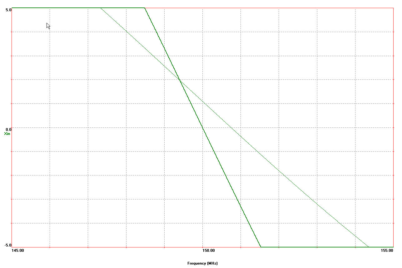
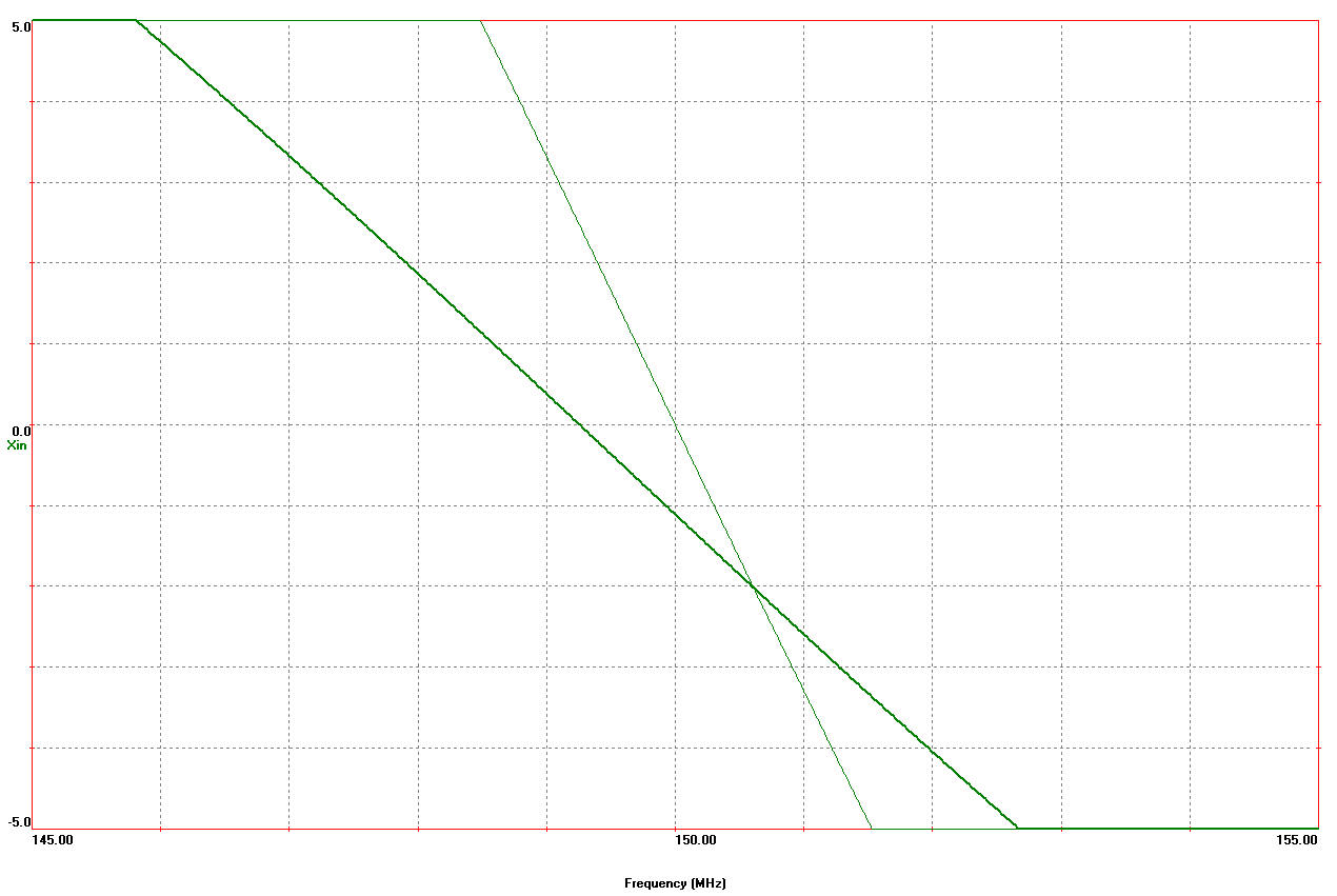
You are right when you are talking about resistance in tank and Q-factor. But there are more than one resistance and the effect from these ESRs may be different and sometimes big enough. Equation for resonant frequency may be derived easily, there is only algebra. Just for illustration purpose I included two screenshots from simple simulation of LC tank. It was done with LINC2 simulator. The first shows the effect of inductive branch ESR and the second shows the effect from capacitive branch ESR. There thick lines are representing expected resonant frequency 150 MHz and thin lines show the actual numbers (when they are crossing zero ohms line). Note now far is the resonance frequency from expected value.

By the way, you are quite right: this is Tomson formula. It is hard to see this name today, but it was popular in the past.

Best regards,
RF-OM
3_1213895067.jpg
90_1213895115.jpg


Added after 27 minutes:

Hello FvM,
I think problem was stated right. There are two questions and you are right: considering Q-factor is the answer for the first one. If you derive the equation for the resonant frequency you discover something interesting. First of all, there is more than one type of resonance and we need different formulas for each of them. This particular discussion is mostly related to anti-resonance. Secondly, the effect from this phenomenon is not always as engineers usually expect. Very often this creates serious problem with physical design and requires new round of prototype. You may ignore this problem, it is easy. But it is better to consider it at the very first stage of design and get your proto done from the first pass.
There are two types of design engineers: the first group considers all design issues carefully, spend right amount of time for analysis and get work done with one or two prototypes; the second type is rush and want to have everything done as quick as it possible and as results spend much more time in the lab with long series of prototypes. I personally prefer to work with the first group and keep the second group guys as technicians. Many years of leading design teams confirmed that this is the most efficient approach considering engineering time and prototyping costs.

By the way what we discus is only the top of the iceberg's. There are some more serious problems with getting right resonant frequency, but this is different topic.
Best regards,
RF-OM
 
Last edited by a moderator:

I agree with FvM that the original problem was poorly worded. It says only "LC" and not RLC or "consider practical issues".

This PowerPoint has an example of including Q in the resonance equation. Page 18 "Effects of RW on fr in Parallel LC",
**broken link removed**

Here's my favorite electronics brain-teaser. It's a trivial circuit with astonishing behavior. Most (perhaps all) simulators and textbooks give a severely wrong answer.
 

All books call such tank LC tank. There is no R elements at all. This was the purpose of this question to ask people to think through the usual things and see something not well known, understand it and then use it in practical engineering life.

Resistive elements may be included into LC tank for special purposes, but it is totally different story.

Let say there are only two elements in tank: chip inductor and chip capacitor. This is LC tank, but Tomson formula will not provide right resonant frequency, more over there may be many different resonant frequencies, tank may work in different modes and so on. Try to draw the equivalent circuit of such tank and you will be surprise. What we discuss now is just a tip of the iceberg. I do not want to go deeply because it is not our topic for today, but you may do it on your own and I am sure you will like it.

Best regards,
RF-OM
 

Your question gives the impression that; the case is ideal - i.e. pure inductance and pure capacitance nothing else. Zero inductor coil resistance, zero leakage flux in Inductor, zero ESR (Effective Series Resistance) of capacitor C, Zero leakage in C, Zero heating losses (of course this is covered under zero resistance), zero radiative losses, Inductor core working in unsaturated region, zero eddy current and hysteresis loss and so on.

If these are the cases,the formula for resonant frequency f=1/(2*pi*sqrt(LC)) is quite correct. No approximations. Whenever the above mentioned elements are considered, more and more impurities will come. Quite natural !!!


Regards,

SUjO
 

RF-OM said:
. Actually the formula above does not tell us the resonant frequency of corresponding LC tank. It provides an approximation. Two questions emerge:

1. Why is resonant frequency only approximated by this formula?
2. How must the formula be changed to get right value for this frequency?

I like to rtespond to this topic because it touches a basic engineering problem:
APPROXIMATION.
In general we can say, that in the world of analog electronics no formula tells us the truth. Everything is only an approximation. That´s not new, but a simple rule and this is, of course, the answer to question No. 1.

However, question No. 2 cannot be answered ! Because in practice there is no answer. Why not ?
Well, an answer can be given only if those non-idealities which have to be considered are named resp. specified. In this context it is to be mentioned that a real capacitor can be modeled using two capacitances, two inductances, three resistors,....(and this description is not complete!). Similar descriptions exist for real inductors. And what about the wires ???

In summary, the question was incomplete and, therefore, calculations to find an answer will always be "wrong". For a real engineering approach the main contributors to the non-ideal behaviour of the tank circuit are to be mentioned.
Otherwise, the question makes no sense.
 

To sujojk,

This question was intended to students who are studying electrical theory. Of course ideal LC tank is ideal, but I asked why we have discrepancies between Thomson formula results and real resonant frequency. This should stimulate thinking and lead student to find the answer. Many of people here found the right answer to the first question: resistance in tank branches are responsible for this effect. In electrical network theory several different types of resonant tanks are discussed. The most common solution to the question will provide analysis of the resonant tank of the first kind. This is the case when resistance is inside both of the branched of single reactance. The very simple analysis provides concise and exact answer to the second question. Simulation with RF simulator confirm this formula to be exact.

My many years observations show that many students and even some of experienced engineers do not know and do not understand this issue well. This was the goal of starting discussion to give students an opportunity to solve this problem by themselves. In this case they will understand and remember it much better than when somebody will show solution. Seeing the formula is not the same as derive it by your own. This is why I do not include final solution here, despite it is easy. Somebody who really interested in this solution can easily derive it. I believe it is better than scan text book pages and post them here.

Next point. It is not just theoretical issue. Engineers who know how to use it will use it. I had cases in the past when we fine tune tanks with variable resistors instead of capacitors and it is helpful to know how to do. But the major advantage is to use this knowledge for everyday design. It is nice to have first pass proto, it isn’t? Of course I understand that this particular knowledge is not enough to have first pass design. But students can learn more. We may do it here if it is really interesting for people here. RF design is art and requires a lot of efforts to learn. Why not to help people with this?

Best regards,
RF-OM

Added after 3 minutes:

To LvW,

Yes, in electronics there are a lot of approximations. But the whole idea of discussion is not approximation (see my previous post to sujojk).

I cannot be agree with your statement that the second question cannot be answered. There is the concise and easy answer, please see the previous post.

Best regards,
RF-OM
 

RF-OM said:
I cannot be agree with your statement that the second question cannot be answered. There is the concise and easy answer, please see the previous post.

Don´t you think, that at least the frequency range of interest should be mentioned by you ?
Only in this case it is possible to decide which parasitic influences have the biggest influence. You only mention resistor losses. But this depends on the frequency ! You know that there are frequency ranges for which a capacitor by its own exhibits resonance effects - independent on a parasitic resistance in the L-branch.

I think the best engineering approach would be
1.) to know about the parasitics within the circuit, and
2.) to decide which non-ideal parameters govern the design- based on the used frequency. And these are not necessarily the resistive losses alone !

Fazit: There is - in contrast to you - no "easy answer" !
 

Dear LvW,

I agree with you now. But please check our past posts. I clearly stated that this particular problem it is just a tip of the iceberg. Of course there are a lot of other factors that have much more influence on resonant frequency. But now we are discussing our topic. I do not think it is good idea to mix all this stuff. Let's students understood the first step and then we may go ahead with next steps. For anti-resonant tank of the first kind there is only one solution and it is easy and concise. I am sure soon you will see it.

Of course the frequency range of our topic is smaller than we can explain with the other phenomenons, but again one step at the time. I afraid that our discussion may completely confuse young students. But we are doing it for them!

Best regards,
Rf-OM
 

About three weeks ago I posted this question. My goal was to show to students and some engineers that there are serious problems with parasitic in RF and microwave circuits and to ask these people to solve the problem. Just a few answered the first question, but nobody took the time to solve the main second question, despite it is not hard to do.

Well, I will provide solution here to show the right answer and to try to wake up an interest to real parasitic problems and how to solve them. This is the only way to have first pass designs.

There are some mathematical expressions involved, so I wrote small white paper and include it as pdf file here. Please keep in mind that this file shows solution only to discussed problem. If you need to count all other parasitic into resonant tank you need much more information. You may found some of such information into this paper: S. Belkin. Design A Tunable Resonant-Tank Circuit. MW&RF. Part 1 May 2001, Page 69. Part2 June 2001, Page 73.
 

Status
Not open for further replies.

Similar threads

Part and Inventory Search

Welcome to EDABoard.com

Sponsor

Back
Top