Continue to Site

Welcome to EDAboard.com

Welcome to our site! EDAboard.com is an international Electronics Discussion Forum focused on EDA software, circuits, schematics, books, theory, papers, asic, pld, 8051, DSP, Network, RF, Analog Design, PCB, Service Manuals... and a whole lot more! To participate you need to register. Registration is free. Click here to register now.

Simple Power Jack Question

Status
Not open for further replies.

torocar

Newbie level 5
Joined
Aug 8, 2006
Messages
9
Helped
0
Reputation
0
Reaction score
0
Trophy points
1,281
Activity points
1,365
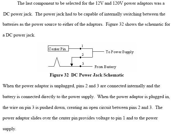
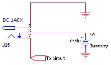
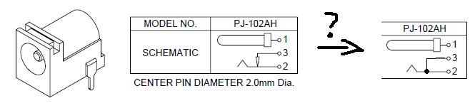
power jack symbol explanation arrow plug

Hi all, I intend to use this connector in a project, however I'm not sure if the arrow means that pins two and 3 are electrically connected. I read an application in which pins 2 and 3 are used for bypassing a batter when power is supplied externally. However the explanation was not clear.

100_1161871437.JPG


Thanks a lot beforehand.
 

torocar,
With this type of jack, pin 1 connects to the center conductor of the plug when the plug is inserted.
.
The pin 2 element connects to the outer conductor (usually common) of the plug.
.
The pin 2 is element spring loaded so that it is connected to the pin 3 element when the plug is not inserted. When the plug is inserted, the plug physically pushes the pin 2 element away from the pin 3 element, thus removing the connection between pins 2, 3.
.
This arrangement is handy when you want to short in input to common when there is no plug inserted.
Regards,
Kral
 

Hi,

Well in that schematic they want to say that Pinc 2 and 3 are temporally conected until you plug the Power connector. In this way you can know when the power cord has been (un)plugged.

Regards,

Carlos
 

Thanks a lot you two for the quick answer. I tried looking at the manufacturer's website looking for this simple explanation... but this kind of info is too elementary for being there. However, it gotta be somewhere...

1. what kind of book or subject does an engineer takes for learning this kind of stuff?

I kept looking for the applications of this jack and I found something kind of useful (but still I didn't understand quite well).

2. Please take a look and give me your opinion:

54_1161890999.JPG


My guess is that the person who designed this was trying to get power from two sources: external adaptor and internal battery. The thing is that I believe when the adaptor is plugged, it is shorted with the battery (since pin 3 is always attached to the battery). Is this an error in the design?

I have made what I think is the correction of the previous image schematic. However, the third pin in jacks is a new topic for me.

3. Can it be used in a situation like this?

98_1161891975.JPG


4. What happens during the short time in which the external adaptor is coming into the jack and barely touches the pins 1 and 3 but the pins 3 and 2 are still closed (that is electrically shorted?. Whould this jeopardize the life of the battery in a long term?. Is there some sort of staggered mechanism that impedes this from happening?.

Thanks again for your attention.
 

This post will be continued in the "Another issue with springed terminal in DC Jack" thread.
 

Status
Not open for further replies.

Similar threads

Part and Inventory Search

Welcome to EDABoard.com

Sponsor

Back
Top