Continue to Site

Welcome to EDAboard.com

Welcome to our site! EDAboard.com is an international Electronics Discussion Forum focused on EDA software, circuits, schematics, books, theory, papers, asic, pld, 8051, DSP, Network, RF, Analog Design, PCB, Service Manuals... and a whole lot more! To participate you need to register. Registration is free. Click here to register now.

[SOLVED] Signal distribution using transistor .................

Status
Not open for further replies.

kdg007

Full Member level 3
Joined
Jan 6, 2012
Messages
162
Helped
1
Reputation
2
Reaction score
1
Trophy points
1,298
Activity points
2,420
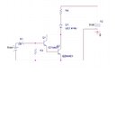
my main object is ..i have 10LEDs i want equal current for all leds with the transistor 2N4401.i came up with this circuit design but not sure which one is a proper way.
Led forward voltage = 1.4(approx in pspice),
Led maximum current for each = 20ma
Vce=0.4
Vbe=0.75
i am thinking the base current is too less for the comparing with collector current(since 1b = 1c/10)
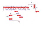
idea 1.jpg
forgot to include R3 resistor (3k) from base to ground ..
so,which approach is better >?i need to recalculate values according to that...i need to built a circuit which can give sufficent current for all 10 leds but i have to use only 2N4401 transistors...any suggestions ?
 
Last edited:
Hi, I just saw your PM. I've been absent from the forum for a long time and there are other messages that I haven't responded to. My sincere apologies for those, especially those asking for help. I have a limited time for forums these days but I'll try to drop in from time to time. I'll start with your problem.

First, what colour of LED do you want to drive? The forward drop Vf is different for different LED types. 1.4V is the approximate value for infrared, 2V for red and amber, and 3V for green, blue and white LEDs. These are approximate values - they change with the forward current and vary slightly between individual pieces.

Second, while it's possible to drive parallel LEDs with a single resistor, it's not really good practice. As said above, the forward characteristics differ from unit to unit. If you simply put them in parallel, current will not be equally shared between the diodes. It's best to have a separate series resistor for each LED.

Thirdly, calculations should be based on the results you want to achieve. One factor is the type of LED as already mentioned. Another factor is how bright you want them to be. If you want them to be as bright as possible, you have to drive them at 20mA each. If you just want them to shine nicely, the current can be just a few mAs.

Think about the points I've raised and decide what you want to do. Then we can start with the actual calculations.
 
Last edited:
  • Like
Reactions: kdg007

    kdg007

    Points: 2
    Helpful Answer Positive Rating
Thank you for replying.
I want to use White leds(Vf = 3.5) and i want upto 20ma of current.
so i kept 61 ohms of resistances for each led as you can see. 5-3.5-0.4/61 = 18ma of collector current.I need Ib=1.8ma with resistance of 2.3k at base.idea 1.jpg.
although i am getting 18ma for each LED,i am drawing 18 x 10 = 180ma collector current from the transistor and i am giving only 1.8ma at the base??is that ok ?
 

If you don't like increasing Ib, we can assume that for 180mA and hfe=100 (180/1.8), Vce = 1V (higher than the typical saturation voltage 0.4).
Re-calculating the value of the LED current limiting resistance, we get:
(5 - 3.3 - 1) / 18mA = 39 Ohm

But now the transistor should dissipate:
Pdis = 1V * 180mA = 180mW
 
  • Like
Reactions: kdg007

    kdg007

    Points: 2
    Helpful Answer Positive Rating
what if i want to keep the Rc as 61 ohms for each LED,what value i should give to the base (Rb and Ib)?
 

Based on the datasheet sheet, for Vce = 0.4V and Ic = 150mA (close to 180mA), Ic/Ib = 10.
Therefore Ib = 18 mA
If you will notice on the real circuit Vce is lower than 400mV, you can lower Ib till you get 400mV.

Added:
Obviously and also on the real circuit, you can measure the actual LED current by measuring the voltage drop on its limiting resistor.
I_led = V / R
 
Last edited:
  • Like
Reactions: kdg007

    kdg007

    Points: 2
    Helpful Answer Positive Rating
yes, for VCE(sat)=0.4Vdc -> Ic=150mAdc,Ib=15mAdc.
for Ib=18mA -> Rb = 5-0.75/18mA = 236 ohms. am i right >?
I dont see Vce = 400mV ? how ?
ALSO ,IS IT OK WITH 18mA FOR iB ? ISNT IT TOO MUCH ?
 

61 ohms is not a common standard value. 56 ohms is, and will result in about 20mA LED current.

You got 2.3k by using the base current needed to drive one LED but you're driving 10 LEDs. If you use 56 ohms each, the total LED current and therefore transistor Ic = 200mA. Using the rule-of-thumb Ic/Ib = 10, we need 20mA base current. To supply that current from 5V, R1 should be about 200 ohms. The nearest standard value 220 ohms should be fine.

You have not mentioned the actual base drive source. If it's really a 5V DC supply, then the values given above are OK. But if you're going to drive it from a digital CMOS IC output, you have to consider one more factor. Most CMOS outputs have a limited output current capability. If you try to draw several mAs from it, the output voltage drops and the source as seen by the load is no longer 5V.
 
  • Like
Reactions: kdg007

    kdg007

    Points: 2
    Helpful Answer Positive Rating
0.4Vdc = 400mV

On the datasheet, Ib=50mA was stated to show the saturation Vce in case Ic = 500mA. So it is not too much for the transistor but it may be so to your input source ;)
 
  • Like
Reactions: kdg007

    kdg007

    Points: 2
    Helpful Answer Positive Rating
61 ohms is not a common standard value. 56 ohms is, and will result in about 20mA LED current.

You got 2.3k by using the base current needed to drive one LED but you're driving 10 LEDs. If you use 56 ohms each, the total LED current and therefore transistor Ic = 200mA. Using the rule-of-thumb Ic/Ib = 10, we need 20mA base current. To supply that current from 5V, R1 should be about 200 ohms. The nearest standard value 220 ohms should be fine.

You have not mentioned the actual base drive source. If it's really a 5V DC supply, then the values given above are OK. But if you're going to drive it from a digital CMOS IC output, you have to consider one more factor. Most CMOS outputs have a limited output current capability. If you try to draw several mAs from it, the output voltage drops and the source as seen by the load is no longer 5V.
-
hmm..i was planning to do that next,but considering your point.What is the best option for me to increase the current to give equal current to all the LEDS. i may want to increase the no of LEDS.
 

There is the darlington configuration (two cascaded transistors with common collector). In this case Ib could be lowered appreciably but Vce(sat) will be higher about 1V. So in this case you need to lower the value of the LED current limting resistor as shown earlier.

In case you prefer Vce be low, you can also use two cascaded transistors but the collector of the first one (say Q1) would be connected to Vcc via a resistor which will supply Ib of the second one (Q2) when Q1 is off.

Note:
For LEDs, I usually use N-channel MOSFET which doesn't need a steady current at its input and driving it with 5V lets its on-state resistance be very low.
 
Last edited:
  • Like
Reactions: kdg007

    kdg007

    Points: 2
    Helpful Answer Positive Rating
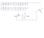
u mean something like this ? i am pretty new to Darlington configuration.can you give any links or explain me how does it works ? and how to calculate the resistor values?
idea 1.jpg
 

u mean something like this ? i am pretty new to Darlington configuration.can you give any links or explain me how does it works ? and how to calculate the resistor values?
View attachment 74381
 

You can see the two transistors as one (having also base, emitter and collector).
But now the forward voltage of the base is about twice the one for a single transistor... The new Vbe is about 1.4V
The current gain is approximately squared (and in saturation mode it is even a bit higher)... you can assume it 10*20. The reason the second term is 20 instead of 10 is that Vce of Q2 will be about 0.4V (Vce_sat of Q1) plus 0.7V (Vbe of Q2), hence Vce (at the output) is close to 1.1V which is higher than the previous 0.4V.
 
Last edited:
  • Like
Reactions: kdg007

    kdg007

    Points: 2
    Helpful Answer Positive Rating
Rb = 5-0.75/0.9mA = 4.7k

In this case it should be modified as:
Rb = ( 5 - 1.5 ) / 0.9mA = 3.9k

Please note that 3.9k includes the internal resistance of the input voltage source.

Also 0.9mA is right if R3 is omitted.

Added:
Rb = ( Vcc - 2*Vf ) / ( Ic / G_current + 2*Vf / R3 )

R1 = Rb - Rs (of the input 5V source)
 
Last edited:
  • Like
Reactions: kdg007

    kdg007

    Points: 2
    Helpful Answer Positive Rating
In this case it should be modified as:
Rb = ( 5 - 1.5 ) / 0.9mA = 3.9k

Please note that 3.9k includes the internal resistance of the input voltage source.

Also 0.9mA is not right... do you know why? It is right if R3 is omitted.
how 1.5v? we cant neglect R3 because of 1cbo is 0.1μAdc.So,how do we get R1..hmmm
 

On my post #16 I was referring to your circuit on #13

1.5 = 2 * 0.75 ... since Ib will pass two PN junctions of Q1 and Q2... right?

I couldn't get your point saying we can neglect R3... what happens if one lets its value be 100 Ohms for example?
 
  • Like
Reactions: kdg007

    kdg007

    Points: 2
    Helpful Answer Positive Rating
According to the Circuit #13 ,if we dont keep R3,wont we have problem with the Icbo current ?
 

Perhaps you didn't notice what I added on post #16

Added:
Rb = ( Vcc - 2*Vf ) / ( Ic / G_current + 2*Vf / R3 )

R1 = Rb - Rs (of the input 5V source)

Added:
I agree with you, it is not a good practice allowing the base of a transistor to float anytime.
But lowering the value R3 requires more current from the input source (about Vbe/R3 more). Vbe=0.75V if 1 transistor, 1.5V if two cascaded ones
 
Last edited:
  • Like
Reactions: kdg007

    kdg007

    Points: 2
    Helpful Answer Positive Rating
Status
Not open for further replies.

Similar threads

Part and Inventory Search

Welcome to EDABoard.com

Sponsor

Back
Top