T
treez
Guest

Hello,
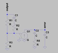
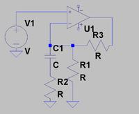
Here are two identical 20W SEPIC LED drivers that use the LTC1871 PWM controller. (Vin=12V, Vout=~45V, Fsw=90KHz, Current mode)
One connects the error amplifier in "voltage error amplifier" configuration.
The other connects the error amplifier in the "transconductance error amplifier" configuration.
The one with the "voltage error amplifier" configuration is far easier to stabilise.
The "transconductance error amplifier" configuration version has to be given an extremely slow transient response in order to make it stable.
Why does the LTC1871 datasheet not recommend the "voltage error amplifier" configuration connection?
It doesn't seem to make sense.
LTC1871 datasheet:
http://cds.linear.com/docs/en/datasheet/1871fe.pdf
Schematics are below...also the LTspice simulations


