Continue to Site

Welcome to EDAboard.com

Welcome to our site! EDAboard.com is an international Electronics Discussion Forum focused on EDA software, circuits, schematics, books, theory, papers, asic, pld, 8051, DSP, Network, RF, Analog Design, PCB, Service Manuals... and a whole lot more! To participate you need to register. Registration is free. Click here to register now.

Offline flyback more stable with big post filter

cupoftea

Advanced Member level 5
Joined
Jun 13, 2021
Messages
2,611
Helped
54
Reputation
108
Reaction score
115
Trophy points
63
Activity points
13,685
Hi,
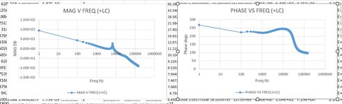
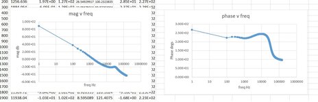
The attached shows a 20W offline 24v flyback (current mode DCM) with and without a post filter. The post filter is 1uF and 10 Farads...so has a resonant frequency well under the xover of the flyback, which is around 1khz.
But as you can see, the post filter actually improves the phase margin.
This is not supposed to be possible, so how is it so?
 

Attachments

  • bode plots _with post filter.jpg
    bode plots _with post filter.jpg
    119.4 KB · Views: 49
  • bode plots _no post filter.jpg
    bode plots _no post filter.jpg
    120.6 KB · Views: 46
"The post filter is 1uF and 10 Farads."
What do you mean? 1uF is nothing as far as an output cap and 10F is huge. I can't make sense of this.
 
Ill send you the excel document in which all this is calculated if you want?.....basically, it uses Choi's document to get the bode plots for a 20w offline flyback, with, and without a post filter...........basically, i wanted to see, at which value of post filter L and C values, it goes unstable. (phase margin sub 20 degrees at xover)....but no matter what value of L and c i use, it doesnt go unstable...so i used 1uH and 10 Farads...to try and get it unstable, but it still didnt go unstable!....i dont like big values of series inductor...as it hits transient response...so chose 1uF.

1uF is nothing
Thanks, i know what you mean, and as you know, even 1uF will very nicely smooth off the corners of those sharp switching current pulses...and 1uF easy to get with low series R....series R not wanted as in transient will cause downward fall in vout for a bit.
 
Why do you worry so much about stability before it's built? Do you need sub % voltage regulation?
I evaluate this on the bench as simulations are interesting but frequently out to lunch.
As you know 1uF MLCC is nowhere near 1uF in practice. The inductor plays a large role in filtering EMC assuming you are running a PI filter and at least 10uH is common.
You seem to keep designing down to microscopic sized part values. Your load's ripple current, if it is the "fan" you were talking about, is not in your simulations.
The larger output capacitor's (you do have them right?) ripple current affects its life, so engineers will oversize the part.
 
1.Why do you analyze filters with unrealistic component values?
2. A simple analysis of output stage + filter transfer function can explain the post #1 bode diagrams. Hint: output stage output impedance isn't zero, therefore you don't see a double pole at output filter resonance.
 

LaTeX Commands Quick-Menu:

Similar threads

Part and Inventory Search

Welcome to EDABoard.com

Sponsor

Back
Top