Continue to Site

Welcome to EDAboard.com

Welcome to our site! EDAboard.com is an international Electronics Discussion Forum focused on EDA software, circuits, schematics, books, theory, papers, asic, pld, 8051, DSP, Network, RF, Analog Design, PCB, Service Manuals... and a whole lot more! To participate you need to register. Registration is free. Click here to register now.

sensitivity of microphone....

Status
Not open for further replies.
ya it would be better if I could filter it in the first stage but my mic sp0103be3 has the first stage integrated with it and I cant change the manufactured package to get a filter in it.... are there any other surface mount microphones without an integrated amplifier or which have accomodation for putting a filter even with the integrated amplifier????

Added after 1 minutes:

HEY THANX KEITH... AFTER PUTTING THE CERAMIC CAPACITORS I AM GETTING THE SIGNAL I WANT AND ALSO BEING ABLE TO USE THE FILTER AT THE SAME TIME....

Added after 9 minutes:

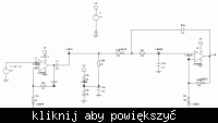
here is my current design... I have used 10uf and 1uf capacitors and using a low pass 2nd order buttersowrth filter at the same time....... my dc offset at the output of the 2nd stage of the opamp stays at around 1.73 volts.. even though I am giving a dc offset of 1.5 volts to the positive end of my opamp...... could it be because of the capacitor at the output of my opamp????
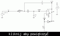
 

The offset (1.73 instead of 1.5V on the output) will be because of the input bias current of the opamp. The LMV721 has around 260nA of input bias current so that will drop 0.26V across the 1M feedback resistor. You may want to reduce the feedback resistors to reduce the offset, although you will need to increase C3 to maintain the same 3dB cut off point (LF).

Keith.
 

    Kinshoro

    Points: 2
    Helpful Answer Positive Rating
I tried reducing the resistances at the feedback to around 8.2k and 1k so that I get a gain of 10...... but it seems when I implement it my opamp output becomes unstable and it constantly varies between 0 and 3v..... without connecting the mic.... and when I connect my microphone to the circuit it starts heating up....................

Added after 1 minutes:

here is the diagram for my current circuit....
 

If you are going to change the gain you also need to change the filter components as their values take into account the gain. If you haven't already got it, download a copy of FilterPro from Texas Instruments web site. It will allow you to experiment with filters/values/gains.

I have attached the values for a gain of 10.

Keith.


    Kinshoro

    Points: 2
    Helpful Answer Positive Rating
In the diagram you attched for the "non-inverting amplifier.JPG" , the + input to the second stage is unbiased. It is probably supposed to get it from R10 , but C5 is in the way :0(
 

    Kinshoro

    Points: 2
    Helpful Answer Positive Rating
ya I did use texas filter pro and that was the design I got for 10 gain low pass buttersowrth filter......

Added after 4 minutes:

Should I try this(diagram)... I have added a potential divider at the output of my opamp so that the dc offset I get is at 1.5v... would this be bad for my mic?? like would this cause the capacitor to reverse the current flow.....
 

ok..... so I connected the potential divider after the 1uF capacitor at the input of my 2nd stage...... but I am still not getting my offset of 1.5v at the output...... but when I connect 1.5v potential at the output it works.... another problem is also when I reduce my gain to 10 and adjust my filter according to texas filter pro and implement the circuit I get from the software my opamp output is not normal....... the output is constantly varying between 0V and 3V...... due to this my mic starts heating up maybe because of the reverse current.......
 

There is no point adding a 1.5V bias point after the opamp. Could you post the latest circuit you have?

Keith
 

    Kinshoro

    Points: 2
    Helpful Answer Positive Rating
this is what my current circuit looks like.... but I am trying to implement the previous one... so that I get the correct dc offset....
 

The current design should be giving you the correct offset: 1.5V DC on the output. It is slightly off because of the input bias current through 1M. Dropping the resistors that set the gain should fix that. I have attached a simulation showing the bias points. I have not used the LMV721 to avoid confusion with the model connections. What opamp are you using in the simulation? The gain should actually be 100 whereas it is 101 which will cause slight gain peaking.

Keith.


    Kinshoro

    Points: 2
    Helpful Answer Positive Rating
ok.... I was wondering if there is a better way to amplify the mic signal..... can it be done using transistors or digitally.... or this is the most preferable way... should I change my opamp and see if it improves???

Added after 34 minutes:

I have noticed one more thing about my 10 gain with 8.2k feedback resistance circuit... not only is my dc offset 1.73v but even my ac voltage amplitude is also quite high at the output even when my mic is not connected........... The ac voltage amplitude is around 2.24 volts............ wouldn't that cause a problem at the output of my opamp....... could it happen because of the way I arrange my capacitors..........
 

Kinshoro said:
ok.... I was wondering if there is a better way to amplify the mic signal..... can it be done using transistors or digitally.... or this is the most preferable way... should I change my opamp and see if it improves???

What is actually wrong with the circuit? I can't see why it shouldn't work fine - it simulates OK.

One thing to watch out for is the choice of capacitors. While you only have a 2 pole filter, but with a lot of gain the tolerances can become important. I normally use COG/NPO capacitors in filters so you need to try to keep the capacitor values low.

Decoupling of the opamps will be important.

I don't think the LMV721 is the best choice for the circuit. It has a limited operating range and you are running from a 3V supply. I would look for something with rail-rail output at least. The choice depends on the frequency range you are wanting to amplify, the amount of gain you want and if you have some current consumption restrictions.

In similar circuits I have use the LT6234 as an initial amplifier but you need to be careful as it has a high bias current. For low current consumption I have used the LMV654 - a bit noisy at 17uV/rt(Hz) but only 122uA per opamp. The noise is fine provided you have some other gain initially.

You need to be clear whether your problems are with the simulations or your PCB.

Keith.
 

    Kinshoro

    Points: 2
    Helpful Answer Positive Rating
well... my problem is with the pcb and in the simulation it works completely fine....... So I guess I will try out another opamp and see if it works better..... well the frequency range I want is around till 20 KHZ cutoff.... and the gain I think will be fine if it is around 10..... one more thing... the dc offset I have given is in my 2nd stage of amplification only... would that be a problem if my first stage is not recieving a dc offset.......

Added after 3 minutes:

AD8603/AD8607/AD8609.... should I try using these for my amplification......
 

OK, if the problem is with the PCB you need to look at things like layout and decoupling. Also double check you have really built what you are simulating - both connections & component values (and polarity of electrolytics if you have any).

It sounds like you may have something oscillating.

It would be useful if you could give the voltages at a few points in the circuit - the two opamp outputs for example. Also, the + and - inputs of the opamps.

Keith.
 

    Kinshoro

    Points: 2
    Helpful Answer Positive Rating
I am actually building this mic for low power battery operated sensor applications. So I need an opamp which is low powered and ideal for this mic...... especially low noise......
 

One other thing - remove the filter capacitors and see if that changes anything. It should still work as an amplifier.

Keith.
 

    Kinshoro

    Points: 2
    Helpful Answer Positive Rating
here are the voltages:-
mic signal before amplifying- 1v around

opamp vin+ 3v
opamp vin- 0V
V- 1.73v
v+ 1.59V
V o/p 1.79V
 

As the microphone has a built in amplifier I would be tempted to set that gain at maximum (20dB) then you can use a low power opamp for the next stage. As I mentioned, I have used the LMV654 and it lived up to its specification. I designed & simulated two 8 pole filters (asymmetric 5+3 pole GIC Biquad bandpass) and it went straight to PCB and worked first time. Very few opamps came close to the performance at that power consumption. They do double & single versions as well.

Keith.

Added after 58 seconds:

Those voltages sound OK if you have a 1M feedback resistor.

Keith.
 

    Kinshoro

    Points: 2
    Helpful Answer Positive Rating
ok. so does it matter if my amplification or gain is different at both the stages and does it matter if the dc offset is different at both the stages of my opamps....?????
 

No, it doesn't matter if the gain is different with both stages. Normally I would split the gain equally between the number of stages unless I was trying to initially boost the signal with a low noise amplifier before a noisier one. In your case you can only get a gain of 20dB from the microphone so unless that will overload the next stage I would use 20dB there.

It is fine to have different stages working at different DC levels and AC coupling between them This is quite common where you might have an opamp with an input range which is not rail to rail, for example.

What isn't so good is to have the DC shift due to bias current in the feedback resistor. The 260nA of the LMV721 is only a typical value. So, if you stay with the LMV721 I would reduce the resistors to reduce that offset. However, if you go for the LMV654 the maximum is 120nA, 80nA typical so it is a less likely to be an issue.

By the way, I missed your comment about the AD8603/AD8607/AD8609 earlier. I wouldn't recommend those - the bandwidth is too low.

It is always tricky doing low noise, low power design. For low noise you want small resistors but for low power consumption you want large ones.

Keith.
 

    Kinshoro

    Points: 2
    Helpful Answer Positive Rating
Status
Not open for further replies.

Similar threads

Part and Inventory Search

Welcome to EDABoard.com

Sponsor

Back
Top