Continue to Site

Welcome to EDAboard.com

Welcome to our site! EDAboard.com is an international Electronics Discussion Forum focused on EDA software, circuits, schematics, books, theory, papers, asic, pld, 8051, DSP, Network, RF, Analog Design, PCB, Service Manuals... and a whole lot more! To participate you need to register. Registration is free. Click here to register now.

sensitivity of microphone....

Status
Not open for further replies.

Kinshoro

Member level 3
Joined
Feb 18, 2010
Messages
60
Helped
0
Reputation
0
Reaction score
0
Trophy points
1,286
Location
Bern
Activity points
1,784
Hello, I have made a non-inverting amplifier using opamp lmv721 or mic preamp for mems mic sp0103be3. The problem is I have amplified it almost a 100 times and the mic also amplifies the signal 10 time...... so I have a total gain of 1000..... so why is it that when I test my signals I get amplitudes of only 4 to 50 mv or sounds such as tapping on the surface of a table and no sound from my voice........ I have attached the circuit here....
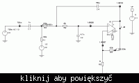
 

I have no idea of micophone's DC bias, it's possibly O.K. for the first stage. The second stage definitely can't work without
a DC bias for non-inverting input. I suggest to correct the filename to "design that cant work"
 

    Kinshoro

    Points: 2
    Helpful Answer Positive Rating
ok so I need to dc bias the positive end of my opamp??? any idea how many volts is ideal for a 3v supply.......

Added after 7 minutes:

is this according to what u want me to do??? dc bias of 2nd stage...... but would this improve the sensitivity of my mic.....
 

I tried simulating with the dc bias but it did not make a difference.... The mic alrady has a dc offset of its own... shouldn't that be enough to make it work....
 

The mic alrady has a dc offset of its own
I was mainly speaking of the second stage. There's still no DC path to the +ve input. Consult an OP datasheet or text
book, how a working amplifier should look like,

I'm partly confused now, if you're talking about real observations or simulation. It sounds like real measurement first. In this case,
you may want to check the real circuit's bias voltage levels.

P.S.: I saw the bias connection now, it has been hard to detect by low schematic resolution. It should work this way. But check
the output levels of both OPs anyway, they should be at about mid-supply.
 

ok... but then if I provide a dc supply to the 2nd stage it should work.... or not??? by 2nd stage I am assuming that u are referring to the 2nd amplifier with a 100 gain......
 

With you cct as shown your negetave input is going to take some time to get to the 1.5V midpoint , due to the large capacitance and 10k and 1Meg resistors. Your simulation could have run it's corse before this happens , so your output will not be what you expect.
I was not clear from your previous posts if this is a real cct or just a sim.
 

I am trying to implement it in real... But I am using a simulator just to see what I get before I implement it.......

Added after 1 minutes:

I have already implemented it in several different ways in real but was not getting the result I expected...... So I had to try simulating and seeing if it works......
 

Hallo,
Maybe you can ask somebody over MEMS from CSEM &/or Hochschule Biel?
K.
 

I have used the Knowles Acoustics active microphones and interface them with no problem. You seem to have three threads on the same subject here!

The Nat Semi LMV721 model has problems as I have already posted

I have also posted a circuit that will work but you abandoned that thread 4 days ago.

Keith.

EDIT: Have you used the recommended interface components from the data sheet? Also, you mentioned a DC offset from the output of the microphone but there is not a specification for that inthe data sheet I have.
 

    Kinshoro

    Points: 2
    Helpful Answer Positive Rating
the dc offset of the microphone depends on the input voltage I am giving to it. The microphone has an integrated amplifier which requires power... I am trying to use it for battery operation so the voltage given as input is around 3v and the output of the mic is at a dc offset of 1v. The problem is my ciruit works fine when I just amplify it. But when I use a 2nd order filter across it my opamp output is unstable and so is the dc offset. I was wondering if my opamp would work properly as a non-inverting amplifier with a 2nd order buttersworth filter..... Instead of integrating the filter with the opamp I have decided to use a first order low pass filter after amplifying the signal...................... Is that ok...........
 

The problem is my ciruit works fine when I just amplify it.
Unfortunately, each of your reports sounds different in detail. I don't think, that I can effectively contribute under these circumstances.

Happy developing!
 

sorry about that... I lost track of explaining things properly... actually what happened was I initially made a mic preamp with an inverting amplifier with a 2nd order bessel filter... but it wasnt working properly because my dc offset to the negative terminal was varying compared to the stable dc offset at the positive terminal... So I decided and according to the advice of Keith to use an opamp which is non-inverting and in that way I did not have to worry about the dc offset at both the terminals of the opamp.... now my opamp is a non-inverting amplifier with a 2nd order buttersowrth filter because it is supposed be better than a bessel filter and my resistances are made for an equivalent reisitance of 10k as compared to that of 100 ohms for my first post. I was trying to match the impedance of the mic and my opamp so that maximum power transfer occurs... but it was not good for the currenct flowing through my opamp and not at all beneficial.... so now the problem with my circuit is that it works well when I am only amplifying the signal but as soon as I use the 2nd order buttersworth filter my output is unstable.. (the dc offset goes upto 0v or 3v and when I use the mic for any audio signal I get an output at my opamp which is constantly varying between 0 and 3v and when I remove the audio signal it still goes on varying.... All this I have implemented in the pcb and also simulated just to see if I am getting what I want...... I hope things are clearer right now for everyone as to what I am doing... sorry... I did not mean to confuse u.....
 

I am slightly concerned about the varying DC offset of the microphone, but as long as it doesn't wander too far I think the circuit I suggested elsewhere is the one to try.

The Bessel vs Butterworth argument depends on your requirements. Bessel preserves the pulse response better (constant group delay) but the Butterworth has more attenuation and is generally a good filter for normal audio.

You are not designing a power amplifier so shouldn't try to match impedances. It is a voltage amplifier. You should have a low output impedance from the microphone and you want that to feed a high impedance.

Keith.
 

    Kinshoro

    Points: 2
    Helpful Answer Positive Rating
well the dc offset of my microphone does vary from .68 to 1.32v when I apply an audio signal to it... but will that be a problem for my circuit????

Added after 4 minutes:

I actually need to measure the positive peaks from my audio signal or just measure a variation in the level of sound or amplitude the mic is recieving.... so would the bessel filter be better for this purpose.....
 

The circuit will track it with no problem. What you lose is dynamic range. If you are running from 3V then you will get maximum dynamic range if you bias your amplifier at 1.5V. At 0.68V you are losing over half the dynamic range. So, if you are wanting the maximum 3V peak-peak output you would need to AC couple the microphone and add a 1.5V bias

Keith.


    Kinshoro

    Points: 2
    Helpful Answer Positive Rating
does the polarity of the capacitors matter............ for ac coupling
 

Yes it does, although for the 1uF I would suggest a ceramic anyway. If not, put the negative to the microphone. For the 10uF put the negative to ground although again, I would probably use a ceramic anyway.

Keith.
 

    Kinshoro

    Points: 2
    Helpful Answer Positive Rating
I only have ceramic capacitors till .1 uF... do they have cermaic capacitors with such high values of capacitance......

Added after 8 minutes:

Actually should I be having any problems if I am using really high values of capacitance of the order of 100uF.... It seems that whenever I use my filter with the opamp... the signal doesnt come out as I want it..... my circuit is only working without the filter.....
 

Yes, ceramics go up to 100uF or more, but probably only in surface mount.

You shouldn't have problems with large capacitors but you need to watch out for a couple of potential problems: large ones have significant leakage which can be a problem if you also have high resistances and if you get too carried away you can end up with circuits that can take minutes to settle after power-on.

If you have a problem you need to be very specific about the circuit you have used and the problem you are seeing. It may be worthwhile using a gain of maybe 10 or 20 for the second stage until you know you need more. If you have a lot of gain and the signals start clipping then things can be problematic. I designed a system with 75dB of gain after the microphone but it had massive amounts of filtering (both LF & HF) and the filtering started early - at the first stage.

Keith.
 

    Kinshoro

    Points: 2
    Helpful Answer Positive Rating
Status
Not open for further replies.

Similar threads

Part and Inventory Search

Welcome to EDABoard.com

Sponsor

Back
Top