Continue to Site

Welcome to EDAboard.com

Welcome to our site! EDAboard.com is an international Electronics Discussion Forum focused on EDA software, circuits, schematics, books, theory, papers, asic, pld, 8051, DSP, Network, RF, Analog Design, PCB, Service Manuals... and a whole lot more! To participate you need to register. Registration is free. Click here to register now.

[SOLVED] Seeking for a simple solution for my simple car DRL connection

Status
Not open for further replies.

sappy2000

Junior Member level 2
Joined
May 19, 2012
Messages
23
Helped
1
Reputation
2
Reaction score
1
Trophy points
1,283
Activity points
1,442
Hi all,

I am a noob here. I am trying to make the DRL (daytime running light) to blink with my turn signal.

So what most people do is cut the ground wire of the DRL and connect it to the positive terminal of the turn signal light. This is result in the follow:

DURING DAYTIME:

When the turn signal is off (positive wire is at 0v)

the DRL voltage different will be +12V, therefore it will be on.


When the turn signal is on (blinking) (positive wire is at 12v)

the DRL voltage different will be 0V, therefore it will be off (blink alternatively to the turn signal)


AT NIGHT when the DRL is OFF:

When the turn signal is off (positive wire is at 0v)

the DRL voltage different will be 0V, therefore it will be off


When the turn signal is on (blinking) (positive wire is at 12v)

the DRL voltage different will be -12V, therefore it will be on (blink with the turn signal)

This works perfect for all the cars with stock tungsten light bulbs..

HOWEVER the problem for me is that my DRL is LED! So -12V is not something I want to feed to the LEDs.


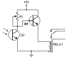
So what is a simple solution? A relay or some sort? Or some chip that can flip the -12V back to +12V?


Thank you in advance for all the people that can able to help me.

Sappy:-D
 

Connet the DRL to the positive and negetive terminal of a bridge rectifier. And Then connect the ac inputs of the bridge rectifier to the points where DRL was originaly connected. The bridge rectifier will make the DRL as a non polarity lamp like tungsten bulbs.
 
You are from which country ?

In most countries where traffic laws exist, only blinking yellow/orange is allowed for turning lights.

Better add multiple high bright yellow/orange leds in turning lights case and make visibility better then ordinary bulb.

I watch "Dangerous Roads" tv show, the same drivers from "Ice Road Truckers" tv show, I'm scary just with watching this driving on city roads in India. If you are from India I dont think that this turning lights can help something while turning somewhere.
 
Last edited:

Hi tpetar,

Thanks for your input, luckily I am from Canada. We are okay to have blinking white LEDs since my car already has orange turn signal.

I would love your input on my case how I can connect the drl to blink. Would you recommend using brige rectifier as well?
 

Optocoupler sens turn signal, output from optocoupler goes to mosfet or relay which power light bulb.

You will just to add one wire to positive turn signal, one wire to positive lights bulb, and one wire for mosfet/relay ground, the same for other side.

Optocoupler should have resistor to limit current for led.

When current on turning lights detected then turn on mosfet and light will on. There is no changes on existing wires, just adding additional wires.

To this you can add phototransistor to make some conditions for night or darknes road conditions like in tunnels...

Something like this:

cir.png

Relay connecting +12V to +12V of bulb.
 
Last edited:
Thanks a lot for your input. Your answer is way more complete than I hope for! I will let you know how it goes. Thanks again
 

Added positive connection, to eliminate confusion.

cir.png

All this can be very small and next to lights. My suggestion is to seal complete electronics with relay with some silicone.
You can add fuse to this or such circuit for dark sense :

https://www.aaroncake.net/circuits/lightdrk.asp

lightdrk.gif


Of course this second relay is not needed all can be implemented in first circuit very well.
 
Last edited:

Thanks for the update again. I forgot most of my symbols. Is that a phototransistor between 85 and 86?

Thanks
 

Thanks for the update again. I forgot most of my symbols. Is that a phototransistor between 85 and 86?

Thanks

No my friend, its relay coil with protection diode.


cir.png
 
Last edited:
Sorry for the noob question again. I have been studying the data sheet of acv13212. So using either micro ISO or 280 should be okay as long as it's the form C? And they have to be diode type?
 

Sorry for the noob question again. I have been studying the data sheet of acv13212. So using either micro ISO or 280 should be okay as long as it's the form C? And they have to be diode type?


No my friend acv13212 is relay, you can use any. My advice si to use relay with higher resistance in coil, this will make lower current consuption. Relays with coil resistance of 300-400-500R will drain at 12V about 25mA-40mA.

Or you can use mosfets instead relays. If you go on mosfets you should provide adequate heatsink for them, what is not case with relays. ;-)
 

Thanks for your advice again, which MOSFET would you recommend for this application?
 

I was thinking to drive the led with this circuit. It's basically a 96 led light strip, draws 80mA
 

Then you dont need relay, thsi can be done with simple transistor or mosfet, and you will reduce number of needed wires, because you dont need higher current wires for power headlight bulbs.
 

I see, another newbie question..

An optocoupler is just a logic inverter? If input is 1 then output is 0, if input is 0 then output is 1?
 

Optocoupler is optoisolator, and can be used for logic state manipulations and signal leveling of course.

cir.png

**broken link removed**
 
Last edited:

Thanks for the link and the updated drawing. I will study them now.
 

Hi there,

I came across a YouTube video. That guy was doing exactly I wanted to do. I have the same led stripe for drl. I don't have an optocoupler but I have a few relay kicking around. Can I do what the guy do in the YouTube? Is he connecting it right? He seems to be short circuiting it when He's doing the turn signal.

https://www.youtube.com/watch?v=2Zho9K3hq1U&feature=youtube_gdata_player


He also has a schematic, seems to be too simple?

**broken link removed**
 

Yes you can. But two things must be checked.

First use relay with higher resistance of coil with smaller current.

Second in most car turning lights automat need adequate resistance/balance between two bulbs, front and rear, if we add more resistance we can get faster or slower blinking of turning lights.

You should try why not.
 

Status
Not open for further replies.

Similar threads

Part and Inventory Search

Welcome to EDABoard.com

Sponsor

Back
Top