Continue to Site
Follow along with the video below to see how to install our site as a web app on your home screen.
Note: This feature may not be available in some browsers.
Knowing phi you have tau. In post #57 I thought about how do you select tau.tau = L/R but without knowing L and R how can I calculate tau ?
Can you tell how you designed it ?
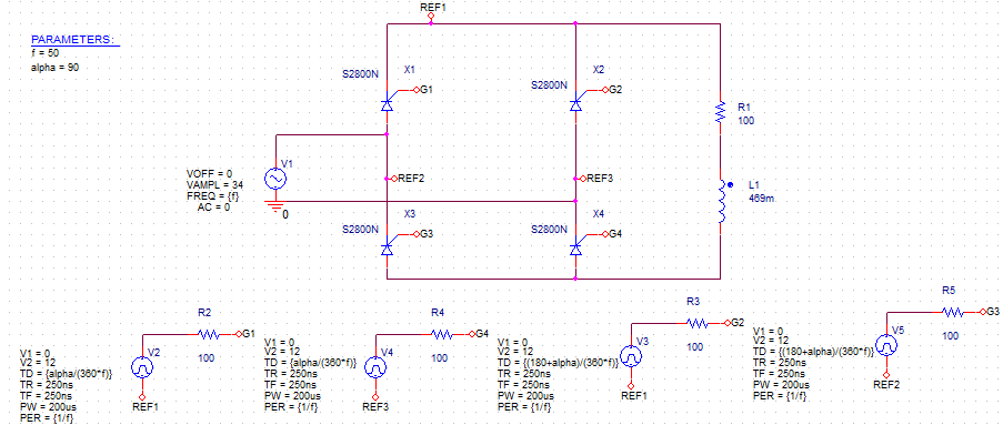
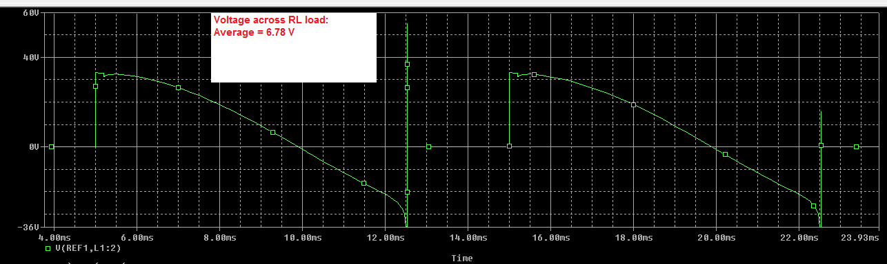
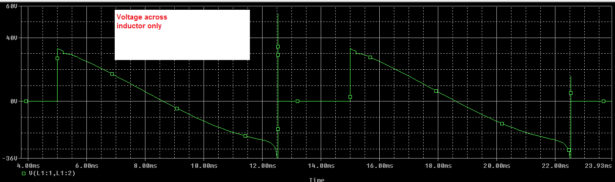
I checked if the already found inductor and resistor can achieve your spec of 28 V peak across the inductor and it turns out it does. In simulation as you can see it is a bit higher....I need to get say for 34V I need to get atleast 28V backemf.
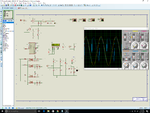
Yes. OrCAD PSpice.Which simulator you used ? Cadence OrCAD PSpice ?
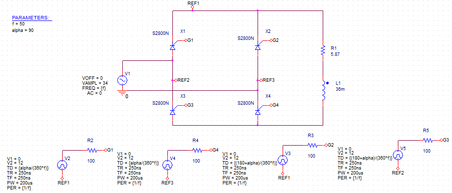

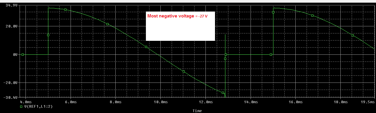

Did you see what "kind of signal for 24 V AC" was shown in post #68 ? Why is not good enough ? You said -28 V, I gave -28 V. What do you want? -34 V ?Edit: I need to get this kind of signal but for 24V AC. The signal shown in image is for 230V AC.
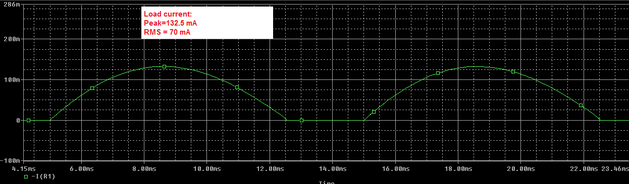
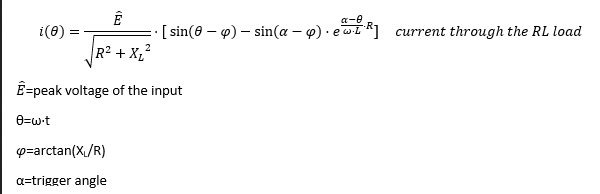
I hope you are joking. You do not know how to measure current in your simulator ?I want to know what will be the current through this RL load ? because it will be good if current is in milliamps otherwise 5W or 10W resistor has to be used I think.
Only if you do a Fourier Series analysis.Should be take f as 100 Hz ?
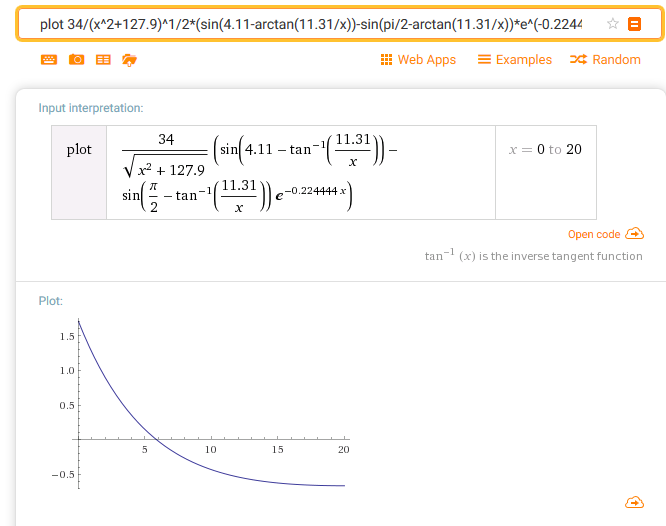
Math tools can easily solve your equations... but it would be useless because are all wrong.Please solve the below equation using math software and tell me the value of R.
50 Hz.what should I take for f ? I am not giving AC 50Hz but I am giving rectified DC which has f = 100 Hz. So, I have to take 100 Hz ?
If the source was DC, but is not the case here.In RL series circuit the current will be max at 5 * tau and if I assume it to be 50mA then current at other times will be even lesser.
After you will have a basic Circuit Theory course, you will understand why.I will try but why my calculation is wrong ?