w_m0zart
Junior Member level 1
weller pu81
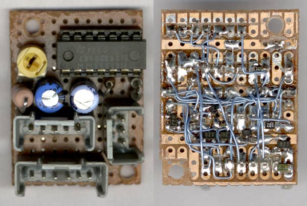
Here is a reverse engineered drawing from a Weller PU81 power unit. It powers a WSP80 soldering iron. I had to find out the schematic in order to check whether the unit is safe to operate.
Apart from the original schematic diagram, I added a temperature standby option, which Weller calls "Stop and Go". It could be made on an extra PCB and connections can be added to the normal PCB without removing any parts/traces.
5 connection have to be made:
- X2 (Vac)
- X3 (GND)
- P.6 LM358
- +5v stab.
- Anode LED (2 color led)
The only thing I changed on the original circuit board was the internal (green) led with a multicolor led, which has a common cathode.
The reference temperature is being set normally with a 2k0 Potentiometer P2, which is connected to a 75k Ohm resistor to pin 6 of the LM 358 op amp. The 75k Ohm resistor is large enough to be overridden by another resistor for setting another temperature, which is in this case the standby temperature.
An optical switch detects when the soldering iron is being placed in its stand. In order to give the unit it's normal function when the optical switch is not connected to the unit, two pins break contact, and disable T103.
The resistor value fore the WSP80 soldering iron can be calculated with the following formula:
R=19.96+0.113*T
(R is in Ohm, T is in degrees Centigrade. Measurement had been done while T<200 degr. Cent.))
Higher temperature I could not measure. However, after some correspondence with Weller, I can confirm the resistor is linear to temperature, even for temperatures higher then 200 degr. Cent.
I hope it helps someone.
w_m0zart