dhruv_electro
Advanced Member level 4
Hi there,
We wanted to design RPM Sensor Signal Conditioning Circuits. We need your comments. Thanks in advance.
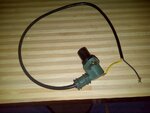
We have RPM Sensors like this:

As far as we know this is VR sensor which produces some analog signal when we place this sensor in front of rotating wheel with teeth.
We googled the detail about the sensor signal conditioning circuit and we found that we may use LM1815. This IC is also available with our local supply.
We tried some designing with the help of google and datasheet from ti website.

Sensor is connected between SIG IN and GND terminal, and output of the ckt will connect the Rising / falling edge of Interrupt pin to MCU. The IRS will count Pulses.
1. Please comment on the above schematic if we missing something.
2. We are considering Rising edge for IRS, should we?
3. We don't know about the purpose of PIN 14 RC Timing ckt, can you please explain?
4. We are confused between using REF Out PIN 12 or Gate Out PIN 10, will you please explain?
5. What are the parameters we need to consider with hardware and software for VR Sensor and mechanical assembly like No of Teeth, Resistance between two terminal on VR sensor.. like that?
6. If there is any better approach exists with VR sensors ckt, can you guide for that?
We wanted to design RPM Sensor Signal Conditioning Circuits. We need your comments. Thanks in advance.
We have RPM Sensors like this:

As far as we know this is VR sensor which produces some analog signal when we place this sensor in front of rotating wheel with teeth.
We googled the detail about the sensor signal conditioning circuit and we found that we may use LM1815. This IC is also available with our local supply.
We tried some designing with the help of google and datasheet from ti website.

Sensor is connected between SIG IN and GND terminal, and output of the ckt will connect the Rising / falling edge of Interrupt pin to MCU. The IRS will count Pulses.
1. Please comment on the above schematic if we missing something.
2. We are considering Rising edge for IRS, should we?
3. We don't know about the purpose of PIN 14 RC Timing ckt, can you please explain?
4. We are confused between using REF Out PIN 12 or Gate Out PIN 10, will you please explain?
5. What are the parameters we need to consider with hardware and software for VR Sensor and mechanical assembly like No of Teeth, Resistance between two terminal on VR sensor.. like that?
6. If there is any better approach exists with VR sensors ckt, can you guide for that?
