Continue to Site

Welcome to EDAboard.com

Welcome to our site! EDAboard.com is an international Electronics Discussion Forum focused on EDA software, circuits, schematics, books, theory, papers, asic, pld, 8051, DSP, Network, RF, Analog Design, PCB, Service Manuals... and a whole lot more! To participate you need to register. Registration is free. Click here to register now.

RF switch Impedance

Status
Not open for further replies.

Atif Hussain Shah

Member level 1
Joined
Jun 11, 2020
Messages
41
Helped
0
Reputation
0
Reaction score
0
Trophy points
6
Activity points
439
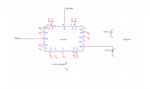
What will be the impedance between output and selected input of an RF Switch? What will be the impedance between output and input which is not selected in an RF Switch?
 

Hi,

we don´t know what switch you use and not the frequency range. So how can we help?
And if we´d know what exact type of switch you use..we need to read it´s datasheet.
I recommend you to read the datasheet.

Klaus
 

Lots of different kinds of RF switches -


So what type are you considering ? Power levels you are trying to switch ? Using
it in modulators ? If so modulation rate and signaling.

Sooo many questions.....


Regards, Dana,
 

Lots of different kinds of RF switches -


So what type are you considering ? Power levels you are trying to switch ? Using
it in modulators ? If so modulation rate and signaling.

Sooo many questions.....


Regards, Dana,
Thanks Dana
I am using ADRF5020 switch. I am switching simple RF Signals around -20dBm power.
 

Hi,

we don´t know what switch you use and not the frequency range. So how can we help?
And if we´d know what exact type of switch you use..we need to read it´s datasheet.
I recommend you to read the datasheet.

Klaus
I am using ADRF5020.
 

Hi,

So you have the partnumber. And you want us to read the datasheet and tell you what's written in....hmm

I already asked you to read the datasheet. You need to do this.
It should be very clear regarding your questions.

If there still remain doubts, please refer to the datasheet. Tell us exactly what you understand (in the datasheet) and what you don't understand.

Klaus
 

Your question is exactly answered by the insertion loss and isolation graphs and s-parameter tables.
 

Hi,

So you have the partnumber. And you want us to read the datasheet and tell you what's written in....hmm

I already asked you to read the datasheet. You need to do this.
It should be very clear regarding your questions.

If there still remain doubts, please refer to the datasheet. Tell us exactly what you understand (in the datasheet) and what you don't understand.

Klaus
Hi,
I have read the datasheet and not asking you to read it.Basically i am facing a problem In testing this switch. My switch is not performing switching operation and i had posted a question that what should be the impedance between output and selected input of switch?
--- Updated ---

I have a problem in ADRF5020 testing. I have set enable pin to ground and Vdd=4.5V, Vss=-2.45V and Ctrl =5V. I have used 1.5kohm resistor in series of CTRL path. My circuit applies Vdd, Vss and Ctrl signals all at the same time and my switch is not performing switching operation. What could be the reason?
 
Last edited:

The relationships between Z and S parameters well understood, if you can
get the S parameters from AD you should be able to compute the impedance's.

Also you have a graph of isolation, you are in a 50 ohm environment, again should
be able to convert that to Z.

Not an expert here by the way.


Regards, Dana.
 
I have a problem in ADRF5020 testing. I have set enable pin to ground and Vdd=4.5V, Vss=-2.45V and Ctrl =5V. I have used 1.5kohm resistor in series of CTRL path. My circuit applies Vdd, Vss and Ctrl signals all at the same time and my switch is not performing switching operation. What could be the reason?
You'd got more specific answers by stating the problem from the start, instead of asking general questions.

You don't mention EN signal. Please review "theory of operation" chapter and table of input signal versus switch state.

Showing a schematic with all pin connections in your setup would clarify things.
 
Hi
Schematic is attached below
 

Attachments

  • ADRF5020 Schematic.PNG
    ADRF5020 Schematic.PNG
    14.4 KB · Views: 94

Get those values from insertion loss ("on" switch)
and isolation ("off" switch) specs or measurements
in a 50 ohm system, at frequency of interest. You
can assume the isolation is capacitive and the
insertion loss, resistive+inductive.
 

It works if you obey all the design rules, you do not need a matching network.
Nevertheless, if you need the impedance, best way that I know is to convert s-parameters to ABCD parameters, then you can observe serial impedance in the B parameter.
You can post your measured s-parameters. Is the insertion loss higher than expected in lower bands around 100 MHz? If so, there is a major mistake somewhere or the device may be damaged. If the performance is fine in low band and gets worse with frequency, then it may be layout or placement problem.
 

Status
Not open for further replies.

Similar threads

Part and Inventory Search

Welcome to EDABoard.com

Sponsor

Back
Top