Continue to Site

Welcome to EDAboard.com

Welcome to our site! EDAboard.com is an international Electronics Discussion Forum focused on EDA software, circuits, schematics, books, theory, papers, asic, pld, 8051, DSP, Network, RF, Analog Design, PCB, Service Manuals... and a whole lot more! To participate you need to register. Registration is free. Click here to register now.

RF Oscillator, need help.

Status
Not open for further replies.

Kz9

Newbie level 6
Joined
Jun 4, 2010
Messages
11
Helped
0
Reputation
0
Reaction score
0
Trophy points
1,281
Activity points
1,360
Hello everyone,

I am trying to desgin RF oscillator.
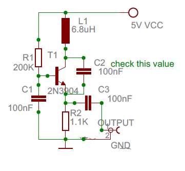
I have 3904 transistors & 6.8uH inductors & lots of resistors & 100nF capacitors.


I tried to desgin it on Multism , it worked, I get sine wave oscillations.
however, when i try to do the real thing, it doesn't oscillate.
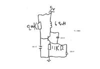
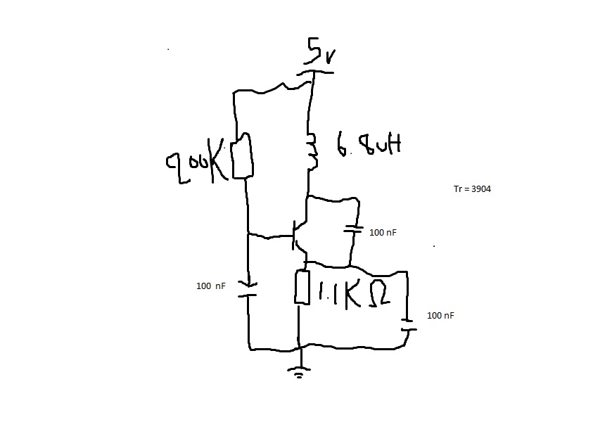
i'll attach sketch desgin of the circuit.

Any suggestions, and explanton how it works please!

P.S: It's Colpitts oscillator desgin

Thanks in advance!
Kz9


Don't decouple the emitter. Instead use it as out put with 0.1 capacitor blocking DC.
check the collector to emitter capacitor for its value. i feel it is too High
a sch is indicated below with the output shown using the cap that was used for decoupling.
27_1275924222.png
[/img]
 

    Kz9

    Points: 2
    Helpful Answer Positive Rating
I can confirm, that the dimensioning is OK (simulation successful).
I know - it doesn't help, but: Do you know Murphy's law?
"Each amplifier will oscillate, but an oscillator does not".
Something in your breadboard introduces parasitic capacitances prohibiting the circuit to work properly. That's all I can say.
(You see, you are not alone with this kind of problem).
 

If I connected an LED to the output, would it light up? or it will damp the oscillations?
or is there a better way to know that it is oscillating?.

I don't have an oscilloscope to observe the oscillations.

Kz9
 

Kz9 said:
If I connected an LED to the output, would it light up? or it will damp the oscillations?
or is there a better way to know that it is oscillating?.

I don't have an oscilloscope to observe the oscillations.

Kz9

only if the oscillator was at a freq of ~ 25Hz or less you you see the LED flickering, any freq higher and the LED will just appear to permanently on
your you know its probably oscillating but you would have no idea of the freq of osc.

Dave
 

There is clearly too much damping in the first circuit shown; it cannot sustain oscillation. With a 100pF capacitor from the collector of the 2N3904 to its emitter and another 100pF capacitor across the 1.1K resistor, it would likely oscillate. The emitter decoupling capacitor could also be larger than 100pF in this case (say, 1nF). Also, the 100nF capacitor from the base to ground could be replaced with a 10nF one.

If all the 3 capacitors were still 100nF, the 6.8uH inductor would need to be replaced with a larger value (so as to increase Q).

If the capacitor from the emitter to ground were omitted, the frequency stability would likely be degraded (due to the fact that the junction capacitances of the transistor would have a greater impact on the frequency in this case), and the circuit might also fail to oscillate.

The base bias resistor (from +Vcc to base) may also inhibit oscillation if its value is too large or too small. For better stability of the oscillator, use another resistor from base to ground and relatively small resistance values for both resistors.

A supply decoupling capacitor (from +Vcc to ground, approx. 10nF...100nF) is also recommended.

EDIT: was "resistor" from the emitter to ground, now "capacitor" (correct).

(added:)
davenn said:
Kz9 said:
If I connected an LED to the output, would it light up? or it will damp the oscillations?
or is there a better way to know that it is oscillating?.

I don't have an oscilloscope to observe the oscillations.

Kz9

only if the oscillator was at a freq of ~ 25Hz or less you you see the LED flickering, any freq higher and the LED will just appear to permanently on
your you know its probably oscillating but you would have no idea of the freq of osc.

Dave
A DC voltage meter will do if its impedance is not too low (otherwise it might damp the oscillations). If you can measure a voltage higher than +Vcc at the collector of the transistor, the oscillator is working. It is also possible to use a diode to rectify the signal from the oscillator and measure the rectified voltage. This way you can also detect any RF signal across the inductor. I think that germanium diodes such as AA117, AA119, OA95, etc. are suitable for HF frequencies, at least.
 

    Kz9

    Points: 2
    Helpful Answer Positive Rating
Thanks, for the clarifications. I've the changed the values according to fg, now it is working :)

Kz9

Added after 2 hours 9 minutes:

On thing else, I connected a germanium diode AA112 at collector and measured the voltage, I am getting 12v from 5v supply, but when I connect the diode in the opposite direction ( Cathode @ collecter ) I'm getting 2v. it means the highest of the oscillation is +12v and lowest -2v.

Shouldn't it be equal or it doesn't matter?


Kz9.
 

Kz9 said:
On thing else, I connected a germanium diode AA112 at collector and measured the voltage, I am getting 12v from 5v supply, but when I connect the diode in the opposite direction ( Cathode @ collecter ) I'm getting 2v. it means the highest of the oscillation is +12v and lowest -2v.

Shouldn't it be equal or it doesn't matter?


Kz9.
When measuring the AC voltage at the collector against ground in this circuit, there is a DC offset equal to +Vcc to be considered. I have also noticed that the readings are different, even after this offset (+5V) has been subtracted (resulting in +7V and -3V for +12V and +2V, respectively). One would expect to get +7V and -7V or other similar values whose sum is zero.

I don't exactly know why the voltages are different but I'm pretty sure that it is normal in this circuit and has to do with the properties of the inductive load at the collector.

If someone could explain why the positive peaks across the inductive load appear to be greater than the negative peaks, I would like to know it also (see the first circuit). (With a PNP transistor and a negative supply voltage, the negative peaks would be greater, as opposed to the indicated NPN circuit.)
 

the biasing is to be adjusted such that the emitter stands at 2.5V while the collector emitter cap is removed. Replace the cap back later

Any measurement is to be taken at Emitter with dc blocking capacitor, the value depends on the frequency under consideration
 

    Kz9

    Points: 2
    Helpful Answer Positive Rating
Status
Not open for further replies.

Part and Inventory Search

Welcome to EDABoard.com

Sponsor

Back
Top