Continue to Site

Welcome to EDAboard.com

Welcome to our site! EDAboard.com is an international Electronics Discussion Forum focused on EDA software, circuits, schematics, books, theory, papers, asic, pld, 8051, DSP, Network, RF, Analog Design, PCB, Service Manuals... and a whole lot more! To participate you need to register. Registration is free. Click here to register now.

RF detector with my comparator

Status
Not open for further replies.

neazoi

Advanced Member level 6
Joined
Jan 5, 2008
Messages
4,123
Helped
13
Reputation
26
Reaction score
15
Trophy points
1,318
Location
Greece
Activity points
36,955
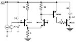
I have built this simple comparator which produces a pattern like a magic eye on a spinning motor which internally has a reset transistor. This is a pov screen

The comparator operated from about 0.5v to 2.5v when feeding DC at its input.
The problem is that:

1. below 0.5v input signal the pattern is switched completely off. So I need something to hold it to that level permanently.
2. I tried a diode voltage doubler at the input, but even if I turned the volume of my sound blaster to maximum, the "deflection" was small. How to cope with this in conjunction with the problem 1??

My intention is to use it as an RF detector so I am posting this on this thread.
 

Attachments

  • Comparator2_schematic.jpg
    Comparator2_schematic.jpg
    21 KB · Views: 158

You need PNP in the diff input stage to common mode to ground.

RF, what freq range are you planning on ?


Regards, Dana.
 

You need PNP in the diff input stage to common mode to ground.

RF, what freq range are you planning on ?


Regards, Dana.

Please give me a suitable circuit.
Freq is less than 100Hz
 

Hi,

I"m confused. 100Hz is far away from being RF.
Please clarify.

Klaus
 

It is a diode envelope detector followed by this discrete comparator. so the comparator works at DC actually, maybe a few 10's of cycles, to cope with the detected AUDIO signal.
I am using discrete general purpose devices in this non-critical application, because they are available here, when I want them, without having to order anything.
So I need to make this comparator as 1 and 2 points in post #1.
You mentioned this pnp, can you provide a circuit for it?
 

This is an LM339, you could eliminate the double PNP's and just use
one stage vs two shown, and current sources substitute an R, all
this would sacrifice G but basically work. Work with spice simulator
to see whats practical.

1607347806579.png


Something like this -

1607349323268.png


But you have not given any specs as to accuracy, drift, supply tolerance, power consumption.....so
experiment until you get the results you want.


Regards, Dana.
 

    neazoi

    Points: 2
    Helpful Answer Positive Rating
This is an LM339, you could eliminate the double PNP's and just use
one stage vs two shown, and current sources substitute an R, all
this would sacrifice G but basically work. Work with spice simulator
to see whats practical.

View attachment 166194

Something like this -

View attachment 166195

But you have not given any specs as to accuracy, drift, supply tolerance, power consumption.....so
experiment until you get the results you want.


Regards, Dana.
Amazing! Thanks! And this will work down to 0v?
 

Amazing! Thanks! And this will work down to 0v?

To within the Voff error due to unmatched transistors. At 100 mV
Vref the error is ~ 70 mV. Also in this bare bones design transistors
going into saturation way too early causing the overdrive needed
to be far greater.

You can buy matched pair transistors, but if you went to that extreme
I would recommend using an actual comparator chip for low error.
Like the one previous recommended, error would be ~ 15 mV.

Regards, Dana.
 
Last edited:

    neazoi

    Points: 2
    Helpful Answer Positive Rating
It worked precisely as you described. Starts to operate from 90mV up to something like 3v. But the upper range (primarily) is determined by the timing capacitor. Great!

Any ideas how to DC bias the Q2 base to 90mV so that it can stay on below this voltage, like there was always a 90mv signal there present, even if no input is applied?
 
Last edited:

The best solution is a constant current source in the diff pair emitters. You can build out
of a pair of transistors off the supply rail. You will have to experiment with its magnitude
and then worst case the whole circuit for headroom, especially if its a production item.
The unmatched gm of transistors, T effects, trying to compare mV signals, is a task for
real professional design, which I am not and IC designer, not even close.

1607387443498.png


Personally I would use a real RR comparator for a production environment.

Good luck.

1607387379333.png


Regards, Dana.
 

    neazoi

    Points: 2
    Helpful Answer Positive Rating
The best solution is a constant current source in the diff pair emitters. You can build out
of a pair of transistors off the supply rail. You will have to experiment with its magnitude
and then worst case the whole circuit for headroom, especially if its a production item.
The unmatched gm of transistors, T effects, trying to compare mV signals, is a task for
real professional design, which I am not and IC designer, not even close.

View attachment 166219

Personally I would use a real RR comparator for a production environment.

Good luck.


Regards, Dana.


I had tried this source, in the previous circuit and it did not do this. What I need is to make Q2 to "think" that there is always a 90mv (or so) signal at it's base, so that my display always stays on, even if the signal applied to the base is lower than 90mv. Then, when an extra voltage is applied to it, the meter will start to deflect. Can I somehow bias the base of Q2 to accomplish this?
 

Hi,

I had tried this source, in the previous circuit and it did not do this. What I need is to make Q2 to "think" that there is always a 90mv (or so) signal at it's base, so that my display always stays on, even if the signal applied to the base is lower than 90mv. Then, when an extra voltage is applied to it, the meter will start to deflect. Can I somehow bias the base of Q2 to accomplish this?

Honest but friendly tone:

How about YOU reading about transistor biasing instead of all these lazy, baby questions you always ask. Where's the spirit of learning stuff yourself? You surely know this, a resistive divider on the base to bias it, very basic BJT/amplifier stuff...

And it seems you were unable to read the application note I provided, I feel I waste time and goodwill replying to your threads.

I hope you credit the other edaboard members who perpetually do a lot of the design work for you on that website of yours.
 

Hi,


Honest but friendly tone:

How about YOU reading about transistor biasing instead of all these lazy, baby questions you always ask. Where's the spirit of learning stuff yourself? You surely know this, a resistive divider on the base to bias it, very basic BJT/amplifier stuff...

And it seems you were unable to read the application note I provided, I feel I waste time and goodwill replying to your threads.

I hope you credit the other edaboard members who perpetually do a lot of the design work for you on that website of yours.

Well let me also write in a honest but friendly tone.

I do give credits always, up to the point that the rules in this forum do not let me to do so (no more credits for today...why?)

A thing that seems simple to you, may not be that obvious, depended on the application. Biasing with a simple voltage divider does not do the trick. How do you "isolate" the voltage from the voltage divider from that of the incoming voltage? A simple diode will do but that will decrease the sensitivity of the input much, which we are trying to maintain.

If you feel that replying is a waste of time for you, please don't reply then, including the kind of message you just posted, cause this...wastes my time.

I have learn so much in this forum throughout the years by asking and discussing with members and sometimes make friends due to this, and I am not going to give up now, not cause of such messages, or otherwise ironic behaviour by some members, including you, that judge people's time and work in experimenting on their websites, just because you are replying on a forum. No I am not going to give up.
And since you are in this forum from 2015 but I am from 2008, I feel that I do not have to apologize about anything to you.
In a honest but friendly tone
Best regards
 
Last edited:

I had tried this source, in the previous circuit and it did not do this. What I need is to make Q2 to "think" that there is always a 90mv (or so) signal at it's base, so that my display always stays on, even if the signal applied to the base is lower than 90mv. Then, when an extra voltage is applied to it, the meter will start to deflect. Can I somehow bias the base of Q2 to accomplish this?

This looks like a requirement for a logical decision, eg. circuit has to have
0 to 90 mV region, then act as a comparator over 91 mV to 2.5V. All made
out of unmatched un-selected discretes but with mV to volt predictability.

Where are you going to get a precision 90 mV reference ?

Without resorting to integrated components, precision reference, I don't think
I can add anything further here with confidence.....Its beginning to look like
an ATTINY85 or PSOC type of solution, but then that has its own issues, like latency
from input to control out....and it has no precision Vref.....its a 10% Vref.

Regards, Dana.
 

    neazoi

    Points: 2
    Helpful Answer Positive Rating
This looks like a requirement for a logical decision, eg. circuit has to have
0 to 90 mV region, then act as a comparator over 91 mV to 2.5V. All made
out of unmatched un-selected discretes but with mV to volt predictability.

Where are you going to get a precision 90 mV reference ?

Without resorting to integrated components, precision reference, I don't think
I can add anything further here with confidence.....Its beginning to look like
an ATTINY85 or PSOC type of solution, but then that has its own issues, like latency
from input to control out....and it has no precision Vref.....its a 10% Vref.

Regards, Dana.
Thanks Dana. Can't it be done with a simple bias somehow of the input transistor, fed from the VCC?
 

Thanks Dana. Can't it be done with a simple bias somehow of the input transistor, fed from the VCC?

Where are you going to get a precision 90 mV reference ?

What accuracy do you want in the comparator ?

What input loading Z do you want that signal source has to see ?

What is the window width the comparator is neither a logic 1 or 0 output
due to finite G thru simple diff stage and buffers (NPNs fed by diff stage) ?

Regards, Dana.
 

Hi,

The requirement for being "discrete" makes it difficult, unprecise, complex and needs a lot of effort.
digikey, farnell, mouser, rs ... and so on ... seem to deliver to Greece.
For me designing a discrete comparator is no option ... especially when I see the time consuming discussions (time is money, we say)

I don´t understand that requirement.
But on the other hand I don´t know the current situation in Greece to get standard semiconductor parts.
Is it really that problematic?

Klaus

All right I see thanks.
I just thought that a simple potential divider on Q2 base, can keep the comparator at the minimum "signal" required to switch on, and then any additional external signal comes at it's base would just keep this 1 state for more time.
My comparator is used along with an RC timing so I am playing around with the time that the comparator output stays on or off.
 

For future reference you could do this with an Attiny85, 8 pin micro,
and get timing accuracy of ~ 1% to handle delays (no external RC needed),
and 10% absolute V compare accuracy (or use ext 3 pin Vref then thats a
small mV inaccuracy).

This is ~ code written using mBlock. You drag and drop blocks of functionality, and tool
converts that to chip (Atmel, Arduino) code and programs chip. Kids in school using this
to do robot programming. I use it to do fast quick and dirty low end designs where
appropriate.

If you use nano board mBlock handles it all. If you decide on ATTINY85 8 pin dip micro
(Atmel part) then you use Nano board to program it. Nano board < $3, ATTINY85 $ 2 - $3.
mBlock is free.

Just so you know there is other versions of GUI programming languages, with other capa-
bilities. For example one you can use Arduino board to do simple talking voltmeter,
freq/period meter, etc. tethering a Arduino board to PC. Snap4arduino.


1607440828947.png


Regards, Dana.
 

    neazoi

    Points: 2
    Helpful Answer Positive Rating
Status
Not open for further replies.

Similar threads

Part and Inventory Search

Welcome to EDABoard.com

Sponsor

Back
Top