Continue to Site

Welcome to EDAboard.com

Welcome to our site! EDAboard.com is an international Electronics Discussion Forum focused on EDA software, circuits, schematics, books, theory, papers, asic, pld, 8051, DSP, Network, RF, Analog Design, PCB, Service Manuals... and a whole lot more! To participate you need to register. Registration is free. Click here to register now.

Resonant circuit 125kHz RFID matching

Status
Not open for further replies.

DominicusPlatus

Newbie level 3
Joined
Aug 17, 2014
Messages
3
Helped
0
Reputation
0
Reaction score
0
Trophy points
1
Activity points
54
Hi

I`m trying to add RFID to my project and due to constrained memory and cost I decided to use classic 125kHz RFID.

Instead of building all the analog circuitry I use HTRC110 interfaced with PIC32.

I calculated resonant frequency for both antennas ( 700uH and 13uF ) and tried them both in circuit implemented according to NXP's AN98080.

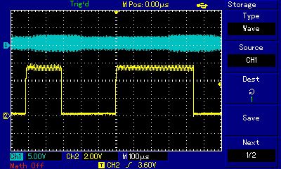
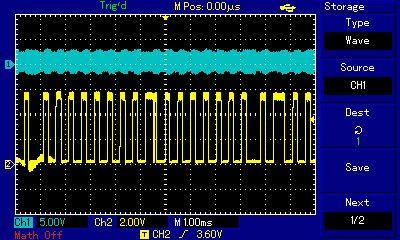
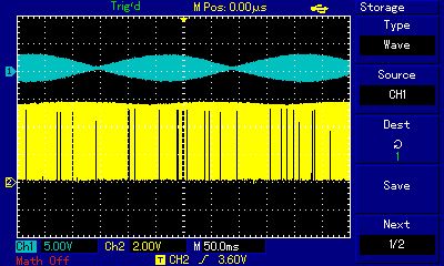
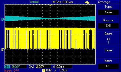
HTRC110 is generating correct square wave signal.

The coil voltage is different from the simulated using the same parameters. Input signal and capacitance are the same so the variation might exists in coil inductance.

I tried verifying the inductance with available method ( Generator + Scope ), but I cannot precisely calculate it this way with given tools ( generator precision low for this range ).

I managed to induct voltage in the coil on very close range ( ~0-2 cm ) where the voltage drop is significant ( 1-3V ).

The coil swing is slightly resembled in digital output, so I moved the antenna coil by 15-20cm from breadboard but it is still there.

Could it be a signal of damaged IC ? Why would there be analog output on serial output pin ?

This is my first advanced analog project and I definietly lack experience for it, but before I get dipper into it I`d like to ask for some hints on this.

How can I make sure that the series resonant circuit is in resonance? I could look for current peak with generator and the same setup elsewhere, but I don`t know how to measure current swing at this frequency without additional advanced circuitry.

Any tips on how can I verify the resonance and possible failure causes ?

PS. Sorry for my English, and I`ll try to give some screens from scope when I find A-A cable :roll: .


Thanks
 
Last edited by a moderator:

If you can choose a small series R to monitor resonance Q should be maximum at 125kHz and result in sine wave with amplification =Q of 100 if total antenna resistance is < 1% of , Z(L) = 6.28 * 125k * 0.7mH= 550ohm thus Ra must be < 5.5 Ohm. If Q=100, the Resolution BW= 1% of 125kHz =1.25kHz.

If de-tuned then low Q will result in low gain and loss of sensitivity.

If your generator does not have 1kHz resolution, then use variable caps or added fixed small amounts to see shift in resonance.

I prefer to use Scope ramp to sweep narrow band FM generator set to 125kHz to display frequency reasons envelope on screen, then attenuate signal from 50 Ohms down to 5 Ohms to given necessary Q.

If coil resistance is too high, then wire gauge is too thin.
 
If it helps, the antennas I use are 'home made' using 42 turns of thin enamelled copper wire (sorry, can't remember the SWG number) wound into a 45mm ring with 50mm long wire tails soldered to make connection to a small 2-pin 'Molex' connector. The tail joints are sleeved then the coil is wrapped in plastic tape to keep it together. It should be 700uH in free space. I use a 22 Ohm series resistor for current limiting and impedance matching.

Works fine for me up to about 20cm distance using standard round or credit card style tags.

Brian.
 

I will try to tune it for Q. Using 10uH the coil resistance of 0.138, the current is quire large as this coil is designed for wireless charging. Resonance is in work but this is not suitable for RFID.
The RFID coil ( 700uH) with series 22R does not resonate with 2.3nF solved for this, so I guess this isnt realy 700uH. Minimum series resonant circuit as in Fig.6 AN98080 has significant current dues to low reactance, 22R is realy loaded. So the optimal setup with another series capacitor solved the problem. I can vary the Ra series resistor for optimal Q.
Matching the resonance with 700uH is quite difficult for me but Ill keep trying to make it work this coil. Although Im still worried about serial output, attached is the oscilloscope with signal on the bottom.
Zrzut ekranu 2014-08-25 o 19.21.03.pngZrzut ekranu 2014-08-25 o 19.21.10.png

Calculations are as follows :
L = 700uH
R = 22

XL = 549.77
C =1/(2*pi*125000*XL) = 2.3159nF
XC = 1/(2*pi*125000*XL) = 549.78 ~ = XL

B = r/2*pi*L = 22/0.004398 = 5002.27

Z = r + (XL-XC) = r = 22

B = r/2*pi*L = 22/0.00439 = 50.11


‚Using the HITAG-transponder family, an upper Q-limit of 20 is recommended’
Q = f /B = 125000 / 5002.27 = 24.988
Q = 20
B = 125000 / 20 = 6250
r = 6250 * 0.00439 = <27.43
Amplitude at the RX-pin is ÛRXmax = 7 V - 8 V relative to QGND

Exactly measuring the DC-supply current (with strong integration) is therefore also a method for finding the exact tuned state.
- DMM

HTRC110 specific :
Connecting Pin 5 (MODE) to VDD enables digital filtering.
In other applications Pin 5 (MODE) has to be connected to GND.

I will tune the circuit and report back.
 
Last edited:

I managed to fix resonance and I verified voltage on RX pin is in range as described in AN. As it can be seen from the screens communication with HTRC is working, I get config written and antena status is ok.
Library I`ve been using is open-sourced by ibexuk. I modified it for PIC32 with timers interupts etc. and comm with HTRC is functional.

Without obstacles, 700u coil circle-shipe tag sized I get 15cm read which will probably be enough.


Read range is good for credit-card sized tags as antenna diameter is about tag length but it cannot read these small finger-sized tags ( they have the same encoding baud etc. but inductance is probably lower). I have tested them on third-party device and it reads them only at touch-contact, so I guess with different dimension of antena I`d get similiar result. ( Currently mine cannot read them at all ).

I`ve been struggling for some time with this looking for failures in hardware but in this case analog front-end indeed was as easy as simple resonant circuit, the actual trouble came with properly setting timers to decode signal and interface 3V-5V high speed logic.
I`m starting to think of using dedicated MCU for sampling/decoding etc. as it takes alot of compute time with all timers required for decoding.

The amplitude of antenna wave is changing with this very low frequency sine-shaped. From all I managed to understand until now, without load in the field ( transponder ) the amplitude of signal should not change, especialy not in this freq. Any one has idea why it can be seen on scope from coil voltage tap point referenced to ground?

I decreased Q from 24 to 14 as suggested and it works well with the exception of small tags.

Anyone has experience with these so called 'Dallas' tags? What would be the optimal antenna size to read cred-card sized >10cm and small ones ? Any one has made some tests?

Thanks
 

Status
Not open for further replies.

Similar threads

Part and Inventory Search

Welcome to EDABoard.com

Sponsor

Back
Top