Continue to Site

Welcome to EDAboard.com

Welcome to our site! EDAboard.com is an international Electronics Discussion Forum focused on EDA software, circuits, schematics, books, theory, papers, asic, pld, 8051, DSP, Network, RF, Analog Design, PCB, Service Manuals... and a whole lot more! To participate you need to register. Registration is free. Click here to register now.

Regarding Negative edge D flip flop with synchronous active low set

Status
Not open for further replies.

Abdul mohsin

Newbie level 6
Newbie level 6
Joined
Jul 11, 2012
Messages
11
Helped
0
Reputation
0
Reaction score
0
Trophy points
1,281
Visit site
Activity points
1,380
Negative edge D flip flop with synchronous active low set

can any one draw the circuit of Negative edge dff with synchronous active low set ..actually i draw the circuit but am getting the wrong outputs by using the tool..so can any one suggest r any link for this cell....
 

i was about to do this for you but i did mine using pass logic, i expect you want full cmos...

- - - Updated - - -

Ok had to go back to the good ole basic cmos digital book, i work more in the realm of analog. but it seems pretty simple to me, if you take a normal negative edge triggered dff made of 2 dlatches, simply break the internal net that connects the 1st dlatch Q to the 2nd dlatch D, insert an and2, make the other and2 input your clrb(clr via inverter). this will make clear bit do nothing until clk goes to 0, at this point the output will be set to 0.
 

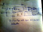
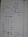
I drawn this circuit would u please suggest me,which book i hav to refer can u give me guidence...am attaching file.check once
 

Attachments

  • Dflop_with_synchronous low_set_Schematic.jpg
    Dflop_with_synchronous low_set_Schematic.jpg
    479.9 KB · Views: 185

Here is a quick barely readable scribble
Dscribble.png

- - - Updated - - -

Opps i just realized you wanted an active low set, not a reset,

to convert use a nand.
 
Last edited:

is it correct brother? am sending as screenshot plz go through it?
 

Attachments

  • Neg edge dff with synchronous active low set.png
    Neg edge dff with synchronous active low set.png
    25.7 KB · Views: 197


Am Abdul regarding Neg edge Dff Synchronous with Active low set.I already send about this cell. But am getting wrong output it is working as latch...can u please give suggestion brot.I am sending screen shot please reply me brother.

- - - Updated - - -

Neg edge Dff waveform.png
Am Abdul regarding Neg edge Dff Synchronous with Active low set.I already send about this cell. But am getting wrong output it is working as latch...can u please give suggestion brot.I am sending screen shot please reply me brother.
 

can you show circuit that you are using for this as well?

- - - Updated - - -

Is hard to believe this is the same circuit, you are showing the output of a d latch changing while the clock is being held constant... is suspicious
-Pb
 

You drew the correct schematic, but the definition of a D latch is that when clock is low Q will not change, the question is why is your latch not working, I would try to verify the latch by itself. possibly you have miss wired in schematic? maybe something wrong with the delays ?
 

You drew the correct schematic, but the definition of a D latch is that when clock is low Q will not change, the question is why is your latch not working, I would try to verify the latch by itself. possibly you have miss wired in schematic? maybe something wrong with the delays ?


Is this circuit correct only na.K Actually i am not missed any wire brother . I am sending Screenshot which i drawn go through once.Neg schematic.png

- - - Updated - - -

You drew the correct schematic, but the definition of a D latch is that when clock is low Q will not change, the question is why is your latch not working, I would try to verify the latch by itself. possibly you have miss wired in schematic? maybe something wrong with the delays ?


Is this circuit correct only na.K Actually i am not missed any wire brother . I am sending Screenshot which i drawn go through once.Neg schematic.png
 

Status
Not open for further replies.

Part and Inventory Search

Welcome to EDABoard.com

Sponsor

Back
Top