Abdul mohsin
Newbie level 6
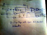
Negative edge D flip flop with synchronous active low set
can any one draw the circuit of Negative edge dff with synchronous active low set ..actually i draw the circuit but am getting the wrong outputs by using the tool..so can any one suggest r any link for this cell....
can any one draw the circuit of Negative edge dff with synchronous active low set ..actually i draw the circuit but am getting the wrong outputs by using the tool..so can any one suggest r any link for this cell....