Continue to Site

Welcome to EDAboard.com

Welcome to our site! EDAboard.com is an international Electronics Discussion Forum focused on EDA software, circuits, schematics, books, theory, papers, asic, pld, 8051, DSP, Network, RF, Analog Design, PCB, Service Manuals... and a whole lot more! To participate you need to register. Registration is free. Click here to register now.

[SOLVED] Reducing Power Consumption on PIC16F628A in SLEEP mode

Status
Not open for further replies.

speedEC

Full Member level 6
Joined
Apr 1, 2011
Messages
337
Helped
23
Reputation
46
Reaction score
21
Trophy points
1,298
Activity points
4,324
Dear All,

I need some help on saving current consumption while the PIC MCU in SLEEP mode. I used three interrupts that is INT0, RBIF and Comparator Interrupts. I have used 6v, 4.2Ah sealed lead acid battery. I have used WDT to wake up the device every 24 Hrs. Until then I put the device in SLEEP mode. After 24 Hrs expires I have to enable comparator to check the Battery Voltage and If Battery Voltage is not low again I put PIC into SLEEP mode.

I have not drawn any current from pins of PIC MCU except drive transistors (RB0 and RB4) as follows:


Code C - [expand]
1
2
3
4
5
6
TRISA = 0b11111111; // All PORTA pins as input
TRISB = 0b00010001; // All PORTB pins as output
                             // except RB0 and RB3 (inputs)
    
PORTA = 0b00000000; // Intialize PORTA
PORTB = 0b00010001; // Intialize PORTB


But, I found so much current consumed by the PIC MCU even though it is in Sleep mode.

Setting Comparator Interrupts as follows.


Code C - [expand]
1
2
3
4
CMCON = 0b00100101; //select mode 7 (101)
VRCON = 0b11101010; // setting Voltage refernce for 1.93v
                              // to select 10
delay_ms(100); // 100 msec delay


WDT Settings - 1:128 prescale

Code C - [expand]
1
2
3
4
5
PSA = 1; // setting prescale to WDT
    PS0 = 1; // PS0, PS1, PS2 = 111 = 1:128 ratio 
    PS1 = 1; // (2.3 seconds delay)
    PS2 = 1;
    CLRWDT();


Disable Comparators before go in to SLEEP mode

Code C - [expand]
1
2
3
4
5
mismatch_Clr = CMCON; // read CMCON to clear Comp.. Flag
    CMIF = 0; // clear Comparator Flag
    CMIE = 0; // disable Comparator Interrupt
    VREN = 0; // off Vref
    delay_ms(100); // 100 msec delay


Put PIC into SLEEP Mode:

Code C - [expand]
1
2
3
4
5
while(1){
    CLRWDT();
    SLEEP();
    Hrs_delay();
}


I wake up the PIC MCU only if 24 hrs expires:

Code C - [expand]
1
2
3
4
5
6
7
8
9
10
11
12
13
14
15
16
void Hrs_delay(void){
 //mSecDelay already set as follows
 //#define mSecDelay 37565 //FOR 24 Hrs = (24hrs x 60min x 60sec / 2.3sec)
 count--;
 
     if (count == 0){ //check for 24 hrs lapsed
         
         count = mSecDelay;  // Reset Counter
            
         mismatch_Clr = CMCON; // read CMCON to clear Comp.. Flag
         CMIF = 0; // clear Comparator Flag
         CMIE = 1; // Enable Comparator Interrupt
         VREN = 1; // On Vref
         delay_ms(100); // 100 msec delay
    }
}


Once if battery voltage is not low again disabled the comparators and put PIC in to SLEEP.

I have to drive one transistor thro' RB4 pin (Vdd) and RB0 (Vdd) to capture IOC and INT0 interrupt respectively.

Any Help pl?

Thanks
 

Dear All,

I could not able to get any timely help from you. But, I went thro' my code many times my self and I found the problem in my code sequence and I rectified my self. Now everything works fine. That is, I have successfully put my PIC into SLEEP and Wake up from SLEEP only everyday morning and enable the comparator to check the battery voltage and if no CMIF flag set for 1/2 an hr then again I put it into SLEEP Mode. This way I have fully reduced the current consumption at great extent.

thanks & bye
 

Dear speedEC,

Will appreciate it if you could share the corrected code.

I am a beginner with PICs, decided on the same PIC you are using, my application is the same, except I need 8hour sleep cycles.

Thanks a lot!
 

Will appreciate it if you could share the corrected code.

I am a beginner with PICs, decided on the same PIC you are using, my application is the same, except I need 8hour sleep cycles.

Thanks a lot!

I will post the code in an hour. If you have any clarifications pl let me know.
 

Will appreciate it if you could share the corrected code.

I am a beginner with PICs, decided on the same PIC you are using, my application is the same, except I need 8hour sleep cycles.

Hi sa_indo,

Sorry for the delayed response. I am in a busy schedule. Thats why I could not able to reply in time. tell me your problem? Do you require comparator code?
 

Hi SpeedEC,
I want to monitor 1 input(Input 1), maybe every 3 secs, if it changes(either up or down) trigger an output(Output 1), low to high, for 1 sec.
Input 2 will monitor state of activated secondary equipment, if it is low, above trigger must NOT activate.
Secondary to that Output 1 must be triggered every 8-hours from last trigger.
Simple, but for a novice that is under pressure to deliver the solution quickly its not that easy.
I will be running the PIC and secondary equipment from a 3.6V (13Ah) Li-SOCl2 battery. I need a 2-year battery life, the secondary equipment will consume less than 1.5Ah over 2-years under the above operating conditions. But the consumption of the PIC needs to be kept as low as possible, 0.5mA will result in 8.5Ah drain over 2 years. With the battery characteristics and temperature variations in mind the realistic available battery capacity will be between 7-8Ah, so I need the PIC to run at less than 0.25mA to ensure 2-year operation.
Once again thank you for your time.
 

so I need the PIC to run at less than 0.25mA to ensure 2-year operation.

For saving current, Select the appropriate PIC MCU. That is, nano watt technology (XLP device). For example, PIC16LF1827, It consumes only 40nA typically when the device is in Sleep mode. Also, you must ensure the device perfectly got into the SLEEP mode. Because, if you source external component from PIC Pins, the device may not go into Sleep mode and consumes more power.

I want to monitor 1 input(Input 1), maybe every 3 secs, if it changes(either up or down) trigger an output(Output 1), low to high, for 1 sec.

Enable appropriate Interrupt Enable Bit and Flag bit. Put the device into sleep mode. It will wake the PIC when changes occurred on PIC pins.

For example, If GIE, RBIE set and RBIF = 0, Interrupt On Change (IOC) interrupt enabled on RB4-RB7 on mid range PIC MCUs (In some other devices can set Interrupt On Change on any individual portB pins, for example PIC16LF1827). So, If changes occurred on any of RB4-RB7 pins, you can check the pin on which changes occurred and trigger the appropriate pin (Low to High or High to Low for 1 sec).

For example, LED connected on RB1 of PORTB. RB4 connected to the device that is to monitor. If IOC occurred on RB4, then you can make RB1 (LED) to High for 1 second and off the LED. You can use any delay routine for 1 sec or timer1 inside Interrupt Service Routine (ISR). But, Timer1 is always preferred. Because, we do not use any delay routine inside ISR in order not to miss any other interrupts.


Code C - [expand]
1
2
3
4
5
6
7
8
9
void interrupt isr(){
   if (RBIE && RBIF){
        if (RB4 == 1){
              RB1 = 1;  // LED ON
              __delay_ms(3000); // 3 SEC DELAY
              RB1 = 0;  // LED OFF
        }
   }
}


Input 2 will monitor state of activated secondary equipment, if it is low, above trigger must NOT activate.

Say for example, secondary equipment connected to RB2. If IOC occurred on RB4 (Input 1) pin, check the status of RB2 inside the ISR before you make the RB1(LED) high.

Code C - [expand]
1
2
3
4
5
6
7
8
9
10
11
void interrupt isr(){
   if (RBIE && RBIF){
        if (RB4 == 1){
              If (RB2 == 1) { // If Input 2, secondary device is high
                  RB1 = 1; // On LED
                  __delay_ms(3000); // 3 SEC DELAY
                  RB1 = 0;  // LED OFF
              }
        }
   }
}


Secondary to that Output 1 must be triggered every 8-hours from last trigger.

"Secondary to that Output 1" -- more explanation required to give suggestion.

if you have any clarification, let me know pl.
 
Last edited:

Hi SpeedEC,
Will you be able to assist in completing this solution.
The application is a GSM tracking unit, I build it myself, design and scripting. I need it completed urgently and do not have the time to learn PIC programming and go through the normal learning process.
If you can please find my company site on Google, in Singapore. Don't want to post contact details on here, but there is an address and mail form on the site.
Thank you.
 
Last edited:

Even though, you are not willing to learn PIC programming for whatever reasons, it may affect you in future. Because, you have to fully depend on others even for a small error. No need to learn PICs program from the basic. But, at least for your coding. Many many experienced persons here to help you by all way along until you successfully finished your project. But, they won't teach us basics. but they can assist us on flow of coding, tell us where the Error occurred, How to solve the error, code optimization, which PIC better for our project, even they tell us basic things on complex code. So, it is better to understand minimal function of your code at least. This will help you forever and also for your future development.

It is better to post your doubts here. You should not depend one person. Many many persons here and they can come together and help you to achieve your goal.

tell me your issue. I am always ready to help up to my knowledge.
 

Hi SpeedEC,
Looks like I have no choice ;o)
Hope you have lots of patience...

I am in the middle of an urgent product design, urgent meaning I have to order components within the next couple of days. Which means I must settle the design before then. Programming etc can be settled over the next couple of weeks.

It is a very basic design, with the intent of using a PIC to trigger another porcessor's power ON line very 8 hours for 1 sec. The other processor will shut down itself after performing certain tasks.
The PIC must monitor an Input, which will be controlled by the other processor, if the other processor is running it will pull down the Input, in which case the power ON line must not be triggered as it is also used to unconditionally shut down the other processor.
A tamper switch must be monitored through an input, any status change will change the status of a seperate output(which will indicate that status to the other processor). This must trigger the other processor's power ON line and keep the output in the changed state for 3mins and only change the state back if the input changed.

As I said, I need to complete the physical design pretty urgently, need to buy the dev and programming kit, then do the programming. Please advise how to proceed. I am based in Indonesia, so can probably get the kits etc only from Singapore.

What do I need and where do I start? :oops:
I had a look at the PIC16F1827 as recommended, 18Pin DIP package is good enough for now, I will re-design and look at space saving later.

I will be using a 3.45V battery with 470uF cap and diode as power supply to both.
The other processor will power a GSM modem.
1. Do I need to split/isolate the power supplies?
2. If they are on the same ground plane, can I drive inputs and outputs directly or do I need to isolate them?

Thanks a lot!
 
Last edited:

Hi sa_indo,

other processor means what? other PIC MCU..? Are you going to integrate SIM module in this project?

Draw a flow chart (using simple word document) and post it here. So that I can easily understand your requirements and provide necessary code.

I will be using a 3.45V battery with 470uF cap and diode as power supply to both.
The other processor will power a GSM modem.
1. Do I need to split/isolate the power supplies?
2. If they are on the same ground plane, can I drive inputs and outputs directly or do I need to isolate them?

If all devices that are using low voltage battery, you don't need to isolate anything.
 
I'm using 1827. Must warn you, this is a very new cpu. PICKIT2 can't debug it, only programming. And MirkoProg can't too. And the simulation model in proteus have many bugs.
 
Hi speedEC,
Will draw that up immediately.
Please see Easyrider83's comment regarding the 1827, will this be a problem?
Thanks again,
 

You can select any mid range PICs. But, we have to keep what Easyrider83 said. First you send your flow chart with requirements and then can select correct and suitable PIC MCU for your project later.
 
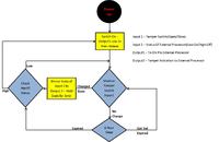
Herewith the FlowChart, hope it is clear enough.
The secondary processor will be the Telit GM862-GPS Modem/GPS module.
Power consumption will be most important, sleep power consumption on the Telit module is 1mA, which will drain the battery.
The PIC will switch the processor on every 8hours, turn on GSM only, receive possible SMS instruction, if none, switch itself off again.
Needs 2-year battery life, powering the combination from a SAFT LSH20 Li-SOCL2 battery (3.5V, 13Ah).
 

I'm used 1827 to make a radio access key. With watchdog turned on in sleep mode power consuption was 7uA. The same result was with PIC18F13k50.
 

Hi speedEC,
Getting worried that I don't hear from you... Was the FlowChart sufficient?
 

sa_indo, I can understand the things only little. I am confused only on 2 yellow boxes and "check input 2" box. It looks simple and you can use PIC16F628A MCU for your project. It will be available easily I hope.

Power On MCU -> Power On GSM Modem -> check the tamper switch status -> If status changed found -> send SMS to the User -> else if no change found on tamper switch - > put GSM and PIC MCU in to sleep mode and start watchdog timer -> If 8 hrs expires -> wake the PIC MCU and check for Tamper switch status -> continue loop.

Is this correct? What is the need of check GSM Modem (Input 2) Status here? and Hold the tamper status for 3 minutes? Output1 low 1 sec and release? I am confused here.

Pl clarify the issues.
 

HI,
Answer your questions first:
1. The Output low for 1s is required on the GSM processor to turn on. It has a seperate from power supply trigger to switch on and off. In order to turn it on/off you need to tie that input low for 1s.
2. The reason to monitor the input from the gsm is that will tell the pic if the gsm is already on, if already on and trigger the 1s pin again it will unconditionally shut down.
3. The reason to hold the tamper output for 3mins isnthatthe gsm needs to start up, go through registration etc before it can read the pins, if the pin changes back before it reads it will not recognise the status change, tamper alarm.

---------- Post added at 09:30 ---------- Previous post was at 09:25 ----------

I will update the flow chart again as soon as I can get back to my pc.
 

Status
Not open for further replies.

Similar threads

Part and Inventory Search

Welcome to EDABoard.com

Sponsor

Back
Top