Continue to Site

Welcome to EDAboard.com

Welcome to our site! EDAboard.com is an international Electronics Discussion Forum focused on EDA software, circuits, schematics, books, theory, papers, asic, pld, 8051, DSP, Network, RF, Analog Design, PCB, Service Manuals... and a whole lot more! To participate you need to register. Registration is free. Click here to register now.

Receiver test setup and calibration

Status
Not open for further replies.

analog_chip

Full Member level 1
Joined
Oct 9, 2011
Messages
99
Helped
1
Reputation
2
Reaction score
1
Trophy points
1,288
Activity points
1,994
Hi,

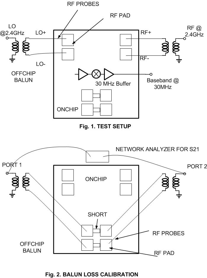
I want to plan test setup of my receiver. My receiver needs RF+ , RF- , LO+, LO- which I am generating using offchip baluns and introducing inside chip using RF probes as in Fig. 1.

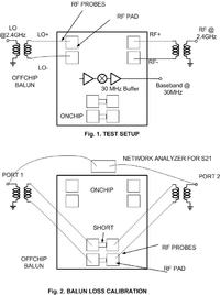
1. I want to calibrate balun/probe loss because I want to subtract it from my total RX noise figure. I have a plan as shown in Fig. 2 where I want to measure the S21, find half the loss and remove it from total NF. The pads are identical, close and shorted. Is that OK? Has anyone better suggestion?

2. I have a baseband buffer @ 30MHz . The input is obviously not matched to 50 ohm. Is it necessary to match the output to 50 ohm @ 30 MHz since it will drive 50 ohm instruments.

3. I want to calibrate the NF and gain of the buffer and hence I have a lonely version. Is it required to matched I/P and O/P at 30 MHz now?


Your procedure suggestion is correct. First it is useful to evaluate all components before testing the complete receiver. Second, make all connections as short as possible to achieve good results.
I think as your chip includes a RF preamplifier an an IF amplifier, matching the following 30 MHz IF will be almost without any effect. For noise figure the loss between RF input connector and RF preamplifier is most important. I would advise to try tuning the input balun at the frequency of interest.
After measuring the NF and RF to IF gain and bandwidth, you can use a calibrated signal generator a 2.4 GHz to test device linearity. You can define P-1 dB point. Make sure your IF 30 MHz post-amplifier has a high enough its P-1dB value. Using a power meter,you can test only your down converter alone.
 

Hi jiripolivka,
Thank you very much for replying. So, according to you I need not calibrate the post amplifier NF and gain since it will contribute very little to total NF.

I also want to know if in Y factor method using spectrum analyzer and noise source you need to match both input and output amplifier to 50 ohm?

The only important condition for NF test in receivers is that the complete chain is linear. No detectors may be included.
For Y-factor method, the important is the output power CHANGE due to the input noise power change. The absolute value of receiver gain is irrelevant.
I do not trust spectrum analyzers for NF testing as the noise level must be averaged (not all SAs can do it) and a typical change is 1..2 dB, so the SA is not too good for it. I prefer using a calibrated power meter.
 

Hi jiripolivka,

Thank you for the reply. I am still not clear. I shall be grateful if you reply as yes or no to this question.
I/P matching required?
O/P matching required?

The reason I want to be careful is that even if you want to know CHANGE in I/P noise power, you should know to what extent input is matched i.e. what FRACTION of input noise power gets into the DUT. Same for the output. If the output is not matched I guess the spectrum analyzer/power meter reading will not be correct because it is not matched to 50 ohm impedance of the spectrum analyzer. The CHANGE will be a function of the ratio.

Again the ration/matching is not the same at input and output. If same then ratio may get cancelled and matching may not matter
 

In low-noise receivers, INPUT matching is important but output matching is not. This is why I suggested that you tune the input balun or whatever matching component you use at the center frequency of interest. By tuning you can see a NF minimum, often at not exactly the designed match. This effect is called noise matching and is often different from power matching.
In very-low-noise amplifiers, certain reactance in the input matching circuit offers a lower NF. You will see for yourself when you try it.
 

Hi jiripolivka,
You are 100 % correct. But you are talking about LNA. I am NOT talking about LNA but a buffer at the end of LNA& Mixer chain to interface to measurement instruments. I want to calibrate out the NF of the buffer. Hence I have a seperate copy of the buffer so that I can find its NF and gain seperately and remove its contribution from the total noise figure.

Now my question is : Is it necessary to match the I/P of this lonely buffer to correctly measure NF?
 

Guys, anybody could advise a commercial SMA balun for 2.4GHz measurements? I've been checking minicircuits, but they have for 500MHz only...
https://www.minicircuits.com/pdfs/FTB-1-1+.pdf

Or am I better to create a simlpe coaxial balun myself? No wideband needed, just for a measurement of some 2.4Gig diff amplifier. What is your experience about this?

Thanks
 

In the receiver chain like yours, the noise figure and gain /loss of each component contribute to SYSTEM noise figure and gain by the Friis' formula. It i good to know NF and gain/loss of each stage.If you need to measure the buffer parameters, you can do it. Measuring gain is easier than measuring NF. For NF test you need some gain after the tested amplifier to make the NF meter or power meter read reasonable values of noise power.

To the balun question, some 2.4 GHz amplifiers are designed as balanced stages. For such devices one can use baluns made of coaxial cable sections, or transformers also offered by Mini-Circuits.

Minicircuits balun transformes go up to 500MHz only...
 

Status
Not open for further replies.

Part and Inventory Search

Welcome to EDABoard.com

Sponsor

Back
Top