Continue to Site

Welcome to EDAboard.com

Welcome to our site! EDAboard.com is an international Electronics Discussion Forum focused on EDA software, circuits, schematics, books, theory, papers, asic, pld, 8051, DSP, Network, RF, Analog Design, PCB, Service Manuals... and a whole lot more! To participate you need to register. Registration is free. Click here to register now.

R2R ladder with OPAMP and controller

Status
Not open for further replies.

Nbj123

Junior Member level 1
Joined
Jul 12, 2019
Messages
18
Helped
0
Reputation
0
Reaction score
0
Trophy points
1
Activity points
164
Hello,

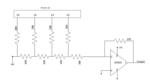
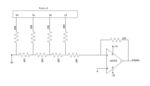
Please find herewith attached an Image of a block diagram.

In this now we are facing that we get output voltage which is range from -2.8 to -0.6 V for (111 to 001 combinations).

But in our application, we want -5V as output. so is there any option to get -5V as output? The controller which we are using is operated on 3.3V. so can we do this by using OPAMP as a differential?

Please guide.
 

Attachments

  • r2r ladder_Controller.PNG
    r2r ladder_Controller.PNG
    17.3 KB · Views: 81

I don’t know how you can get -2.8v, never mind -5v, out of +7v and an opamp.
 

Hi,

we have given ladder output to inverting pin of OPAMP so it convert postive to negative.

Thanks
--- Updated ---

hi,

Sorry updated the wrong block diagram.

Please find attached the updated block diagram.
Thanks
 

Attachments

  • r2r ladder_Controller.PNG
    r2r ladder_Controller.PNG
    17.8 KB · Views: 81

Hi,

you are operating the opamp in an inverting manner, where it is converting the current flowing towards the negative input into a corresponding voltage by

\[{V}_{\mathrm{out}}= -{I}_{\mathrm{in}} \cdot{R}_{\mathrm{f}}\].

Where the input current is equal to the current flowing through your 20 k\[\Omega\] feedback resistor (\[{I}_{\mathrm{in}} = {I}_{\mathrm{f}}\]). So as you can see, increase \[{R}_{\mathrm{f}}\] accordingly to gain an output voltage of -5 V.

BR
 

Hi,

You say you want -5V output. I doubt this really is what you want. But if so, then use a -5V voltage regulator.

More likely you want to extend the output range minimum voltage to be -5V.
In this case simply increase the feedback resistor

Btw: there are countless descriptions on how a R-2R ladder DAC works. They also explain range setting and calculations.
They also show a correct schematic. Yours is faulty (besides non standard Opamp symbol and missing junction dots) your b0 has no effect.

Look for reliable documents. Best are: application notes from semiconductor manufacturers and from universities.

My personal opinion:
I see no benefit in building a DAC this way. It is not accurate, has low precision and low resolution...and for this high part count.
I'd rather use PWM for simple, low frequency ...or buy a cheap IC.


Klaus
 

You should also correct the R2R ladder. Presently b0 is shorted, insert 20 k termination to ground.
 

A useful reference (Analog Devices Data Conversion Handbook), attached.


Regards, Dana.
 

Attachments

  • Analog Devices Data Conversion Handbook 2005.pdf
    30.9 MB · Views: 63

Status
Not open for further replies.

Similar threads

Part and Inventory Search

Welcome to EDABoard.com

Sponsor

Back
Top