Continue to Site

Welcome to EDAboard.com

Welcome to our site! EDAboard.com is an international Electronics Discussion Forum focused on EDA software, circuits, schematics, books, theory, papers, asic, pld, 8051, DSP, Network, RF, Analog Design, PCB, Service Manuals... and a whole lot more! To participate you need to register. Registration is free. Click here to register now.

Question about NPN Transistors

Status
Not open for further replies.

STTrife

Newbie level 5
Newbie level 5
Joined
Feb 23, 2015
Messages
8
Helped
0
Reputation
0
Reaction score
0
Trophy points
1
Visit site
Activity points
82
I am working on a small hobby project and I ran into something that I don't understand, I hope someone can explain it.

I'm trying to control a remote control device with a PIC. Now I managed to make this work, with the help of some diagrams I found online, but there's one aspect I don't get (why it's working).

I tried it with the off and on switch on the remote. There are 3 pins/lines involved with these buttons. (say line A, B, C). When line A and B are connected, the on-button is activated, when line A and C are connected, the off button is activated.
Line A has +3.3 v over B and also over C. No voltage between B and C

Now to control this, I found a design with a PIC and 3 transistors, which works, I have attached the diagram:
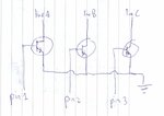
remote.jpg

The two systems (remote and PIC) have separate power supplies. The ground in the diagram is only the ground of the PIC, not the remote control.

Now I understand that when I set Pin A and Pin B HIGH, that the first and second transistors are 'open', but how can current flow from line A to line B? It would have to go trough the second transistor in the wrong direction... right??? how is that possible?

Thanks for any information!
 

I think you've got this all wrong. And your explanation is a quite confusing. How are the buttons connected, exactly? What are "pin 1, pin2" etc.? What is connected to the collectors?
 

i'm also same think about it "barry", if diagram of "line A,B,C" are we given Vcc then all the transistor are working as transistor as a switch and if it is so it's all about related to Digital subject so these all transistor are act as OR gates......
 

I think it's almost meaningless to discuss the transistor circuit details without knowing the exact parameters of the connected remote control. If the circuit works only with separated grounds (if at all) it should be replaced by a better considered circuit.

A transistor can switch signals of "wrong polarity" up to a certain voltage and current level, e.g. be used as a "poor man's" analog switch. But there are better options in most cases and better suited components available.
 
pin 1, 2, and 3 are general IO pins on the PIC.
I don't know the exact details of the remote control, since I didn't design that, but what I could find out: there's one microcontroller in the remote. If you push on the ON button it will connect 2 pins of that microcontroller (I called them Line A and Line B, but maybe I'll call them pin A, B and C then), if you push the OFF button it will connect PIN A and PIN C.
So right now the the 3 pins on the remote controller (this is just something I bought, it's an external device, hence the seperate circuits), are collected to the the collectors, 3 pins from my own PIC are connected to the base, and the emitters are connected to the ground of my PIC.

As I said I don't know much more about how the remote control works, I don't have a circuit diagram of it or anything, and the microcontroller is not labelled, so I have no idea what it is exactly and how it works. But I just need to 'simulate' a button push on that remote, by doing the same thing as a normal button push would: connect 2 pins of the microcontroller of the remote. My idea was to use relays, but then I found this design with transistors, and it does work, but it's confusing. I don't know what to do with remarks like "I think you've got this all wrong", it's more useful to tell me what information you need to make my question more clear.
I didn't know that the wrong polarity current can also flow trough a transistor, but it seems like bad design then, is that bad for the transistors? It would explain why the design works tough.
What components do you think I should use to simulate a button press on the remote controller?
Any other advice?
Thanks!
 

If you don't know the signal direction of the lines A-C, an analog switch or transfer gate would be an universal solution. E.g. CD4016 with 4 analog switches. If you know that one pin is driving out and the other receiving, also a logic gate. Common ground of both circuits is presumed.
 
A remark like "I think you've got this all wrong" is telling you that you have failed to communicate your issue properly. I DID tell you what information we needed. And it's STILL not clear to me what you are doing. You are connecting the collectors together with a switch? You are using the transistor bases as an input to your PIC? Or you are using the PIC to drive the base, but shorting the collectors together? I just don't understand.
 

When switching a load on the low side to ground, the grounds MUST be connected with with remote load connected Vdc power.
Common ground connection is essential.

All transistor switches of single stage are inverting by nature, so that a logic high input connects the load to ground.

This is the most common IC for doing this, which consists of 7 darlington NPN with protection clamp diodes for blocking inductive spikes.

ULN2003 aka. "the hammer driver" switches
Logic-Diagram-of-ULN2003[1].jpg

The Emitters (E) are all tied to ground and ground at both ends must be connected.
Common refers to the remote supply voltage for clamping spikes exceeding V+ when the switch opens on inuductive loads.
 

A remark like "I think you've got this all wrong" is telling you that you have failed to communicate your issue properly. I DID tell you what information we needed. And it's STILL not clear to me what you are doing. You are connecting the collectors together with a switch? You are using the transistor bases as an input to your PIC? Or you are using the PIC to drive the base, but shorting the collectors together? I just don't understand.

Something like that last part. PIC pins are connected to bases, the pins from the IC on the Remote control are connected to the collectors, and the emitters all go to the PIC ground.
"You got this all wrong" is not the same as "I don't understand your question or your design"... it's just a vague comment about me doing something wrong, when you don't even understand what I'm saying, so how can you tell I got it all wrong? And I just copied the design from... https://www.instructables.com/id/Bu...p5/Designing-the-remote-controller-baseboard/, and as I said it does work, so I think saying "you've got this all wrong" is not really the best remark...
 

Many Instructables and maybe this one were designed by a 10 years old kid who knows NOTHING about electronics. Then the projects "got it all wrong".
In this project the bases of the transistors are missing series current-limiting resistors.

You got it all wrong because you connected your Arduino PINS to the bases and connected your LINES to the collectors. The Instructable has the Arduino PINS connected to collector resistors that you do not have and the LINES are connected to the bases.
 

Read what he wrote in the comments:

* B goes to resistor (10K& - 22K&) then to Arduino digital pin.
* E is the common pin between all NPN transistors. This will go to Arduino GND pin.
* C connected directly to each pin on the A/C remote control lines.

He drew it weird, or he had transistors where the pins are different or something...
 

Hi AG,

I think you might be wrong this time. As quoted from the site:

* You need to identify the E, B and C pins of that NPN. I used the multimeter to do so. (Sorry, I didn't explain this here. You can youtube it)
* B goes to resistor (10K& - 22K&) then to Arduino digital pin.
* E is the common pin between all NPN transistors. This will go to Arduino GND pin.
* C connected directly to each pin on the A/C remote control lines.

I think the author was using Japanese transistors where the collector is in the middle and the base is on the right when viewed with the numbers facing you. It could be 2SC1318 or something.

But it's true that the OP didn't connect resistors on the bases of the transistors.

Allen
 

Sorry i did use resistors on the bases, but i forgot to draw them in.
 

Status
Not open for further replies.

Part and Inventory Search

Welcome to EDABoard.com

Sponsor

Back
Top