Continue to Site

Welcome to EDAboard.com

Welcome to our site! EDAboard.com is an international Electronics Discussion Forum focused on EDA software, circuits, schematics, books, theory, papers, asic, pld, 8051, DSP, Network, RF, Analog Design, PCB, Service Manuals... and a whole lot more! To participate you need to register. Registration is free. Click here to register now.

Question about igbt module and resistor

Status
Not open for further replies.

jmx66

Member level 5
Joined
Nov 16, 2010
Messages
93
Helped
0
Reputation
0
Reaction score
1
Trophy points
1,288
Location
France
Activity points
2,045
Hi all,

I plan to use an igbt module , in order to replace 6 discrete igbt burnt, on my bldc card.

Power 1500 W V bus: 340 V Rated current 4,5 A

Which component is best suited for the job:

**broken link removed**

**broken link removed**

**broken link removed**

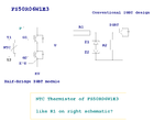
Also i'd like to know if resistor between T1 and T2, has same function than R1, on a "conventional" design.

See draft joined.


Thanks a lot.

jm
 

Attachments

  • igbt-design-300x300-ech200.png
    igbt-design-300x300-ech200.png
    28.3 KB · Views: 118

The thermistor is intended for module temperature measurement (for overload/overtemperature protection), you should find it's purpose mentioned in the datasheet. You'll find typical gate series resistances suggested in the datasheet along with switching characteristics, they have to be added for typical gate driver circuits.
 
  • Like
Reactions: jmx66

    jmx66

    Points: 2
    Helpful Answer Positive Rating
I've just read the data, and found Rgon and off : 8,2 Ohm.

In datasheet from other manufacturers , this value is in the last row.

Thanks a lot.

jm
 

Suggested Rgs are usually representing a tradeoff. Increasing the value, also using a weaker driver, results in increased switching losses, but also less overvoltage transisients and electromagnetical interferences. Placing a too small gate resistor value in a badly designed circuit (with long wires between IGBTs and bus capacitors etc.) can result in damaging the IGBTs by voltage transients. With low inductance snubber capacitors (e.g. FKP types) placed near to the "Sixpack" modules, overvoltages can be managed effectively.
 
  • Like
Reactions: jmx66

    jmx66

    Points: 2
    Helpful Answer Positive Rating
Thanks a lot for your very clear answer.

In fact, if i remember a previous datasheet read - about Mitsubishi , i think -, in igbt you can have :


- Rg on and Rg off with different values

- Rg only for "on-state and off-state"

- Rg datasheet value is the minimum, and you can increase to value x 2


About driver , i plan to use FOD3120, with Vge about 15V, for use of Zener diode overvoltage protection about 18V.

FOD 3150 has lower ouput current than 3120, so better driver , as you told about weaker driver; time longer to charge gate -emitter and gate-source capacitors, so less transients?

Just read on FOD 3150 datasheet:

The FOD3150 is a 1.0A Output Current Gate Drive Optocoupler capable of driving most 800V/20A IGBT MOSFET !!!!!!

So bad choice :sad:


Z1 and Z2 of Vz= 18V and 47 KOhm-1W, for discharging gate.

Zener diode from NXP

NXP|BZV85-C18|DIODE, ZENER, 18V, 1.3W | Farnell United Kingdom

See draft.

Is it right or wrong, as usual?

About igbt , it's a steep learning curve, but really interesting:!:

Thanks.

jm
 

Attachments

  • FO_FOD3120-1.pdf
    380.4 KB · Views: 120
  • igbt-design-300x300-ech200.png
    igbt-design-300x300-ech200.png
    28.3 KB · Views: 126
  • FOD3150.pdf
    353.1 KB · Views: 82
Last edited:

It's no problem to use a stronger gate driver as long as the intended gate current is set by Rg. Asymmetrical gate resistors are sometimes used, particularly in high power electronics where efficiency is squezed up to the edge. You should also notice the difference between unipolar (e.g. 0/12V) and bipolar (e.g. -12V/12V) gate drive and check which is referred in a datasheet. High power is using exclusively bipolar drive, for medium power and simple home appliances (e.g. washing machines VFD), it depends.

The zener diode should never conduct in normal operation and isn't critical, the diode capacitance possibly matters in combination with small & fast IGBTs.
 
  • Like
Reactions: jmx66

    jmx66

    Points: 2
    Helpful Answer Positive Rating
Status
Not open for further replies.

Similar threads

Part and Inventory Search

Welcome to EDABoard.com

Sponsor

Back
Top