socratidion
Newbie level 4

- Joined
- Apr 9, 2013
- Messages
- 5
- Helped
- 0
- Reputation
- 0
- Reaction score
- 0
- Trophy points
- 1,281
- Activity points
- 1,352
I've been working through 'Make: Electronics', and I'm having some trouble understanding how experiment 11 works. I'm completely new at all this, so I hope this makes sense to you. The circuit is like this:
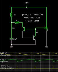
6V dc: from positive goes to a 470K resistor, then a 2.2microfarad capacitor, then back to negative.
Between the resistor and the capacitor, a branch goes to the anode of a PUT, which has its gate set at about 4V (by some other stuff which isn't important).
From the cathode, it connects to an LED, and then back to negative.
I hope that's simple enough that I don't need to draw it. The idea is to make the LED flash intermittently (somewhere around once a second, give or take). It works OK, and I've had fun substituting different values of everything to see how it affects the frequency of flashed. Fine.
My question is: why is the voltage from the battery insufficient to overcome the threshold of the gate?
I mean, the idea here is that the gate won't open until the capacitor has charged up to just over the threshold set at the PUT gate, i.e. 4V. Then it discharges, passes through the PUT and lights the LED. But why isn't the PUT anode getting full 6V from the battery anyway? The 470K resistor shouldn't have any effect on the voltage at the anode, because both the PUT and the capacitor are infinitely resistant (until the gate opens).
The author sometimes says things like 'the capacitor sucks current…' Does he actually mean this? Am I to imagine that voltage from the battery is diverted to the capacitor until the capacitor is sufficiently charged?

