aht2000
Junior Member level 3
I am trying to use QUCS to simulate the input and output impedance of a simple common emitter amplifier based on BFP420. As this is new to me, I would like to verify with the experts if the steps I performed are the right ones.
- I created a schematic with the amplifier I want, and updated all the parameters of the transistor with the one from Infineon (the built in QUCS spice mode was not giving correct DC bias and current results as per actual physical implementation).
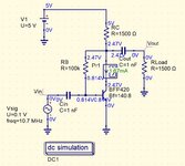
- Performed a DC analysis to get the VCE and IC at which the transistor is operating. I verified the same with LTSpice and got similar results for DC bias. See attached "DC Bias.JPG".
- Based on the VCE and IC, I selected the corresponding S2P file from Infineon website. See attached "BFP420_w_noise_VCE_2.5V_IC_1.5mA.s2p".
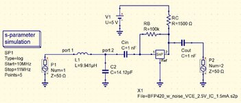
- I replaced the transistor in the schematic with an s-parameter file component, and edit the component to point to the .s2p file. See attached "S-PAR Sch.JPG".
- I used the built-in s-parameter.sch template from QUCS to complement the existing schematic with the correct simulation and graphs.
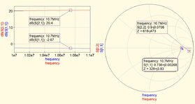
- I ran the simulation and got the attached S11 and S22 results at 10.7MHz "S-PAR S11 S22.JPG".
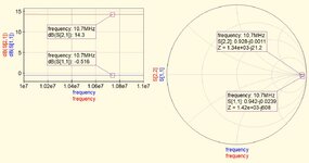
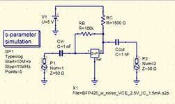
- From the smith chart graph and clicking on the S11 marker, I selected the "power matching option" to create an LC matching to have an input impedance of 330 ohm (output of the a Murata 10.7 ceramic filter). See attached "S-PAR Sch with 330 ohm inp match.JPG" and "S-PAR S11 S22 with 330 ohm inp match.JPG" for the results.
- I can see that now I am getting the required input impedance but the S22 and output impedance has changed. I then tried to put a matching network at the output to match a 1500 ohm (the input of an SA612 mixer) but then the input impedance changed.
- I remember reading earlier that the input and output matching network affect each other, and it may need some kind of iterative approach to reach the required input and output.
- Are these the correct steps to follow? I do not thing that QUCS has a feature to adjust by itself both input and output matching networks taking into consideration the interaction between them.
- Is there another free simulation SW that can do that?
- If none, would I just have to decide which matching network is more important to my use case and live with the consequences?
- Is there a way to reduce the interaction between the input and output matching networks to almost nil? This will be my best case scenario.