Continue to Site

Welcome to EDAboard.com

Welcome to our site! EDAboard.com is an international Electronics Discussion Forum focused on EDA software, circuits, schematics, books, theory, papers, asic, pld, 8051, DSP, Network, RF, Analog Design, PCB, Service Manuals... and a whole lot more! To participate you need to register. Registration is free. Click here to register now.

purpose of RC network

Status
Not open for further replies.

asim63

Newbie level 5
Joined
Mar 29, 2012
Messages
9
Helped
0
Reputation
0
Reaction score
0
Trophy points
1,281
Activity points
1,354
hello all,
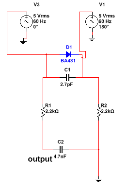
attached is a file in which there are two inputs (having phase difference) across the diode. after that there is a series RC network and the output is across C2 (output labeled). what is the purpose of this RC network in this circuit.. whether it is filter or impedance matcher or something else.
it is basically a part of receiver circuit and in actual instead of two voltage sources there are two receiving antennas and i am modeling those receiving antennas with voltage sources just to check the behavior of the circuit.
thanx to all....
2_1347775349.png
 

Hi Asim
For a receiver ? i think that is detector section , but i don't think your simulation is correct ! because you are simulating that with 60HZ . anywhere , that is a PI filter as a ripple detector ( push ).
ABout it's frequency perhaps you are working on navigation systems ??
Best Wishes
Goldsmith
 

thnx sir,
it is receiver circuit that will receive reflected EM waves at around 400 MHz. i m testing at different frequencies just to check the behavior but unable to find out the purpose of RC network. if it is pi filter what is the purpose of C1? using which formula i can testify the above given values as this circuit is not designed by me..
best regards...
 

etwork. if it is pi filter what is the purpose of C1?
Hi again
Aren't you familiar with 2nd order filters ? that capacitor will give lower input resistance . and of course , this circuit will have sharper response .
reflected EM waves at around 400 MHz.
How about your message signal ? what is it's frequency ?
i can testify the above given values as this circuit is not designed by me..
I don't think that , it will be a good idea , to test that circuit with 60 HZ frequency , because this frequency is ( this pretty low frequency ) for military communications , and detecting such low frequency is completely different .
Any where , what you have expected from that circuit that you couldn't see ? for my opinion with 60 HZ it's behavior won't be acceptable .
All the best
Goldsmith
 

I'll stop further thinking about the original circuit, when I see that you supply 14 Vpeak forward voltage to the diode and blow it.
 
  • Like
Reactions: LvW

    LvW

    Points: 2
    Helpful Answer Positive Rating
thnx alot sir
actually i m student in RF field and it is my first task..so i don't have much knowledge...at the output of this circuit another circuit is attached but my task is only to find out the signal at this point.
it is basically a receiver, as i told earlier, that receives reflected (transmitter will send EM wave of 380 MHz and that wave will be reflected after colliding any dielectric) EM wave of 380 MHz. this receiver will detect phase difference using diode. after detecting phase difference, the RC network comes, now according to my little knowledge, in low pass pi filter there are two capacitors and one resistor.but i am not able to understand that this cap-resistor-cap-resistor network will do.whether it is low pass or band pass filter. suppose we don't know the frequency of incoming signal.. is it possible to find out the frequency at which this circuit is designed using the above given parameters?

- - - Updated - - -

sir plz explain working of this network. in fact push me in a right direction so that i start working. thnx
 

wave of 380 MHz an
But you told 400 MHZ at first
will detect phase difference using diode
Is your mean that your waves are out of phase together ? if yes , in your simulation both are the same , perhaps you have changed it internally ?

whether it is low pass or band pass filter
That is low pass .
suppose we don't know the frequency of incoming signal.. is it possible to find out the frequency at which this circuit is designed using the above given parameters?
We can easily find cut off frequency , but i don't know why you don't know anything about it's input signal ( it's frequency ) .
Before trying to help you more , can you tell , that , is that your homework , or it is just a hobby ?
 

sir this is an extra task just for learning purpose..i have to analyze it therefore the information is not clear, i have to perform a rough sketch how i can analyze such kind of circuits. how i can find the filter types, how i can roughly estimate the values through frequency or frequency through given values... in fact u can say i have to sketch a procedure how i will analyze this circuit.

- - - Updated - - -

if it is lowpass, i guess the cutoff freq should be 1/2*pi*R1*c2. ? mean C1 is for reducing ripples and the R1 and C2 are making lowpass filter? m i right? than what is the purpose of R2? perhaps as this circuit doesn't have rectifier, so the R2 is for the other half cycle of the input signal? m i right sir?
 

Asim63, the circuit as shown with your first posting makes no sense in case the input signals are derived from (ideal) voltage sources (internal resistance zero).
In this case, these voltages appear also at the top of both resistors - independent on the existence of the diode in parallel with the capacitor (which are, therefore, useless).
You need to collect more information about the signal sources and their source impedances.
 

sir , this is a passive receiver circuit, there are two antennas instead of voltage source. but when signal will strike on antennas, it will induce voltage. therefore just to model that voltage i have placed voltage sources here. my purpose is just to find out that how i can calculate the values of Resistors and Capacitors in this configuration. thnnx,,, best regards
 

sir , this is a passive receiver circuit, there are two antennas instead of voltage source. but when signal will strike on antennas, it will induce voltage. therefore just to model that voltage i have placed voltage sources here. my purpose is just to find out that how i can calculate the values of Resistors and Capacitors in this configuration. thnnx,,, best regards

A receiver circuit needs a kind of rectifying circuitry.
I repeat: In your circuit with voltage sources the diode is useless - it has no effect!
 

will it not make differential input?
 

A receiver circuit needs a kind of rectifying circuitry.
I repeat: In your circuit with voltage sources the diode is useless - it has no effect!

More than that - even C1 and R2 will have no influence on the node you have named "output". It is just a first order RC lowpass - that's all.
 

dear sir, u mean it's low pass filter with cutoff freq 1/2*pi*r1*c2 ? is it?
suppose if we ignore diode and there is a sinusoidal voltage source across C1..what will happen?
thnx and best regards
 

dear sir, u mean it's low pass filter with cutoff freq 1/2*pi*r1*c2 ? is it?
suppose if we ignore diode and there is a sinusoidal voltage source across C1..what will happen?
thnx and best regards

The voltage across C1 does not matter.
The lowpass consisting of R1 and C2 is driven by V3 only (if the source internal resistance is zero).
The lowpass has a cut-off frequency of approx. 15 kHz - thus, a frequency of 380 MHz will be attenuated by approx. 80 dB.
 
  • Like
Reactions: asim63

    asim63

    Points: 2
    Helpful Answer Positive Rating
thank you so much sir,, if you think there is something else which can help me in this circuit or in this field too..plz guide me... now i m very much clear and trying to simulate it in multisim and then will shift to ADS for complete transmitter receiver architecture.
best regards
 

Status
Not open for further replies.

Part and Inventory Search

Welcome to EDABoard.com

Sponsor

Back
Top