asim63
Newbie level 5

hello all,
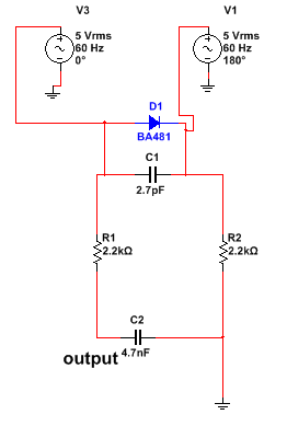
attached is a file in which there are two inputs (having phase difference) across the diode. after that there is a series RC network and the output is across C2 (output labeled). what is the purpose of this RC network in this circuit.. whether it is filter or impedance matcher or something else.
it is basically a part of receiver circuit and in actual instead of two voltage sources there are two receiving antennas and i am modeling those receiving antennas with voltage sources just to check the behavior of the circuit.
thanx to all....


