Kryptone
Member level 3
Mr. BaWa,
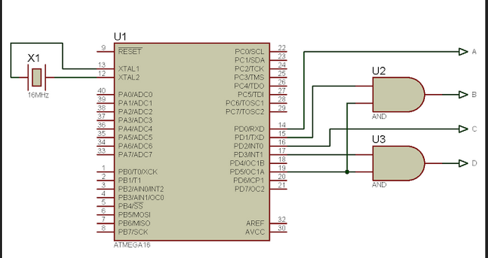
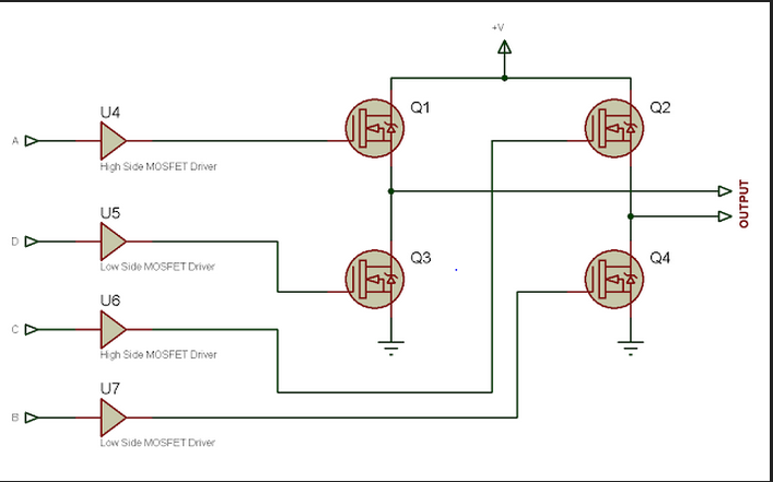
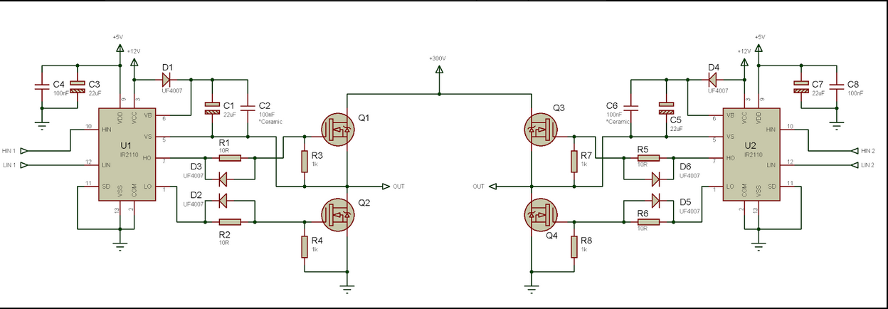
Here is the schematic for my DC-dc converter
I however used 4 Mosfets ie. I paralleled one with the high side Mosfet and the other with the lowside Mosfet
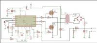
And by in series with the h-bridge you mean in series with the inductor?
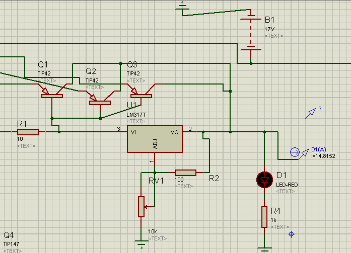
I got a 75W, 120V incandescent bulb and connected it cross the 10uF,400V electrolytic capacitor and it did not light up and the transformer began to make a sound and the voltage fell from 180Vdc to about 2Vdc. What could be the problem????
could it be because the electrolytic cap doesnt have a low ESR?
Please help!!!
Last edited: