Continue to Site

Welcome to EDAboard.com

Welcome to our site! EDAboard.com is an international Electronics Discussion Forum focused on EDA software, circuits, schematics, books, theory, papers, asic, pld, 8051, DSP, Network, RF, Analog Design, PCB, Service Manuals... and a whole lot more! To participate you need to register. Registration is free. Click here to register now.

Pulse generator 2-20ns

Status
Not open for further replies.

Siniša

Full Member level 6
Full Member level 6
Joined
Jul 14, 2002
Messages
383
Helped
87
Reputation
174
Reaction score
18
Trophy points
1,298
Location
Windsor ON Canada
Visit site
Activity points
2,692
I am trying to design pulse generator with adjustable width 2ns-10ns and adjustable amplitude up to 20V. I am not sure what solution might be best to achieve these specs, so far I found Jim Williams AN98, figure 12.
If anyone has better configuration suited for this, please let me know. Also are there BJT's with 0.5A/30V that have low capacitance <3pF? What PNP /NPN would you recommend for this application?
Also in this AN what is purpose of D1?

Thanks!
 

Jim Williams was one of the best if not the best analog designers in the industry and his designs are likely to work. His passing was a great loss to the art of analog design.

D1 was likely added empirically to improve the pulse rise-time characteristics.

Don't offhand know what 30V switching transistors are available for the task. You would want some with switching speed and capacitances similar to those specified.
 
  • Like
Reactions: Siniša

    Siniša

    Points: 2
    Helpful Answer Positive Rating
To achieve 20 V output, you are looking for RF power transistors with >= 1 GHz fT. RF MOSFET, not yet available when the classical genrator circuits have been designed, are an interesting option, too.

No suitable RF PNP transistors available with Vce,max > 15V.

I think it's better not to stick with this particular circuit.
 
  • Like
Reactions: Siniša

    Siniša

    Points: 2
    Helpful Answer Positive Rating
Thanks to both of you for replying. Yes, it looks like D1 is shaping pulse and that is probably primary reason for 500mV amplitude. FvM, could you suggest some circuit or AN as starting point?
 

BJTs of 20V range barely made 1GHz fT when last I worked
in bipolar technologies (pre-SiGe). SiGe devices as a rule are
optimized for low voltage operation, rarely better than the
CMOS BVdss with which they travel.

I think in this case you might prefer to use a low voltage
high frequency capable device, and a pulse transformer.
Turns ratio to get the voltage scaling between driver swing
and desired amplitude. You do not indicate the load, I'd
guess you intend 50 ohms.

Now one neat thing about the pulse transformer scheme
is, you can get to narrower pulse widths by out-phasing
two drivers (H-bridge) than you probably can pass through
one driver, itself. Phase control rather than pulse width
control. Of course then the other edge might get up to
some funny business, but you might (say) create a logic
that allows a phase difference on the leading edge and
ensures none on the falling / reset edge.

Xfmr also breaks the link between positive voltage, and
needing to then use an inferior (high side, P type) switch.
Though you could also consider a pulse transformer driven,
GaN FET (EPC has very fast, 100V range enhancement
mode devices with low Cgg) source follower / switch style
for this.
 
  • Like
Reactions: Siniša

    Siniša

    Points: 2
    Helpful Answer Positive Rating
I would look at half bridge with 1ns rise time with 50 ohms in series.

Obviously you need to specify your load which affects everything.

- some bridge drives have 8ns Tr with 1000 pF load so with 50 Ohm and 0pF, you can expect rise times down to 1ns with crossconduction control built-in as essential. Then drive with ECL XOR to vary pulse width using variable RC delay.


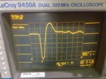
FYI, I generated this 8ns pulse with picosecond risetime on 50 Ohm scope but limited by 1ns risetime of 300MHz scope using a special avalanche effect with HVDC, but not variable PW or useful for you.

but you may need to consider all avalanche devices , non-saturating to get 2-20 ns.

whats all this stuff for (anyhow)?
 

Attachments

  • image.jpg
    image.jpg
    1.8 MB · Views: 113
  • Like
Reactions: Siniša

    Siniša

    Points: 2
    Helpful Answer Positive Rating
Thanks SunnySkyGuy, what driver would you recommend? Yes, fast avalanche front edge is very easy to obtain, I was able to get tr 220ps without special selection of device, just some UHF npn I had on hand. (When 1ghz scope's contribution was calculated out). As you pointed, pulse width is problem in this application.
Dick_freebird , what core would you recommend for this application for xformer? Thanks for EPC suggestion, first time I come across them. I will explore this option. I came across Ixys rf driver that was close, but no CIG.
 

What is the load impedance?
What pulse rep rate?

This summarizes the state of the art of pulse generators from the retired President of Pulse Labs

PSPL Pulse Generator and Pulse Amplifier Capabilities
riseT | Amp| Rep. Rate | Technique | Example Models
2.5 ns 20 V 165MHz discrete Silicon RF Transistor 12000
250 ps 50 V 100 kHz Avalanche Transistor 10300B
125 ps 2.5 V 1.6 GHz custom design MMIC 12020
100 ps 35 V 100 kHz Step Recovery Diode 4500E
45 ps 10 V 100 kHz Step Recovery Diode 10050A
25 ps 8 V 12 GHz custom design MMIC 5865
20 ps 250 mV 50 kHz Tunnel Diode TD1107
20 ps 2 V 25 GHz custom design MMIC PPA
8 ps 2.5 V 45 GHz custom design MMIC 5882
< 5 ps 5 V 500 kHz PSPL Non-Linear Transmission Line 4016

Good luck finding those transistors
https://www.overunity.com/12736/kapanadze-cousin-dally-free-energy/dlattach/attach/115338/
 

Attachments

  • State of the Art ps Pulsers.pdf
    724 KB · Views: 152
  • Like
Reactions: Siniša

    Siniša

    Points: 2
    Helpful Answer Positive Rating
If anyone has better configuration suited for this, please let me know. Also are there BJT's with 0.5A/30V that have low capacitance <3pF? What PNP /NPN would you recommend for this application?

Thanks!
The app note indicates a NPN/PNP pair consisting of 2N6304/2N5771. I would stick with the recommended transistors.
As mentioned by other poster, Jim Williams was the best among the best analog circuit designers, and he had extremely clever designs which would include the component parasitics to his advantage.
 
  • Like
Reactions: Siniša

    Siniša

    Points: 2
    Helpful Answer Positive Rating
Hi Sinisa, some designs use a programmable delay line to generate programmable pulses in the range from 1ns to 64ns in 0.25ns steps, like the iC149 pulse generator for laser driver. The datasheet shows the structure: https://www.ichaus.de/upload/pdf/iC149_datasheet_A2en.pdf . The output signal can be used to drive the output stage.

Enjoy your design work!
 

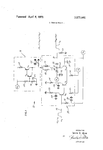
This patent is interesting , looks like Jim Williams used this for AN98 fig12 I referenced earlier :)

US3573502-1.png
HTA, thanks, I actually have sample quantity of iC-HG that was one of the options if I figure out what to drive with this. This chip could potentially drive transformer if I could locate suitable core to do 12.5Ohms:50Ohms unun. That board actually uses neat Maxim chip for creating delay that has reference delay as well.

GaN FETs from EPC are amazing devices, although cumbersome for prototyping , both for sourcing and soldering. Good luck trying this in improvised "wires in air" setup :)

**broken link removed** was fastest bridge that I could find, but it still is short in Tr even with no capacitive load. If anyone has suggestion on faster bridge than this ?...

Also,does anyone have example of circuits where avalanche pulse width was extended beyond storing capacitor charge? And any idea how to reduce tail in such circuits?

:thinker:
 
Last edited:

Status
Not open for further replies.

Similar threads

Part and Inventory Search

Welcome to EDABoard.com

Sponsor

Back
Top