jony130
Full Member level 3
pspice abm schmitt trigger
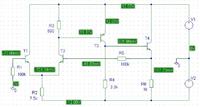
I got this "simple" (not for pspice Orcad 9.2) circuit :

And pspice calculate the bias point and is all Ok.
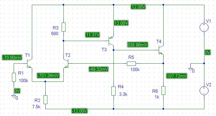
But if I change the circuit a little bit (positive feedback).
Then pspice show that I don't expect.
This is a bias point that calculate the pspice
I even build the circuit to assure the correct answers because I was a little confuse.
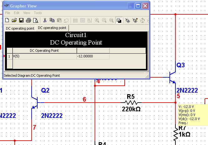
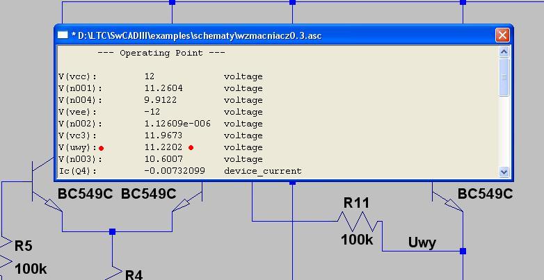
Only LTspic and multisim show the correct answer.
So here we have another example that pspice sometime is wrong
I got this "simple" (not for pspice Orcad 9.2) circuit :
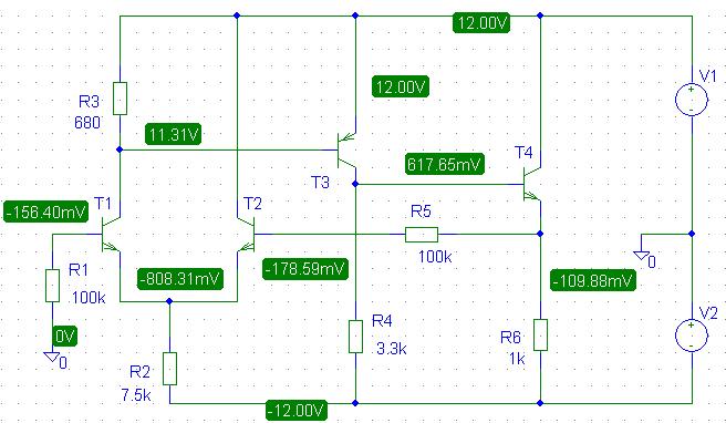
And pspice calculate the bias point and is all Ok.
But if I change the circuit a little bit (positive feedback).
Then pspice show that I don't expect.
This is a bias point that calculate the pspice
I even build the circuit to assure the correct answers because I was a little confuse.
Only LTspic and multisim show the correct answer.
So here we have another example that pspice sometime is wrong