Continue to Site

Welcome to EDAboard.com

Welcome to our site! EDAboard.com is an international Electronics Discussion Forum focused on EDA software, circuits, schematics, books, theory, papers, asic, pld, 8051, DSP, Network, RF, Analog Design, PCB, Service Manuals... and a whole lot more! To participate you need to register. Registration is free. Click here to register now.

Proximity sensor

Status
Not open for further replies.

tnnedaboard

Member level 3
Joined
Apr 5, 2012
Messages
64
Helped
0
Reputation
0
Reaction score
0
Trophy points
1,286
Activity points
1,748
Hi,

I made a proximity sensor with this IR emitter LL-503IRC2V-2AD and this phototransistor LTR-3208E
wavelength 940nm.

it works well, except if I expose it to sunlight both directly and indirectly ...

can you recommend something to solve?

can I put a filter in front of the window where the emitter and the phototransistor are located?

it is urgent thanks ...
 

Are you trying to detect presence/absence of an object or distance to
object ? If later distance range desired, min/max.

Regards, Dana.
 

You should not work with analog level detection of light, but rather digitally, sending/receiving pulses with a known pattern.
 

Hi,
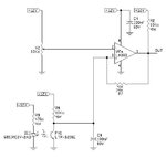
this is the circuit I currently have:

how can i change it to avoid this problem?

SENS.jpg
 

Pulse the LED current at several KHz.
Filter the output from the sensor to eliminate other frequencies.
Rectify the resulting waveform. It will be proportional to the proximity but far less sensitive to fixed light levels hitting it.

Brian.
 

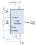
I'm sorry is this okay to power the 1khz emitter?

I have a 53% dutycicle okay anyway?

ne555 astabile 1khz.jpg

can you tell me the filter?
 

so can it fit?
I have a doubt about the filter on the receiver out ...

SENS_new.jpg
 
Last edited by a moderator:

Hi,

Now you are at more than 20 parts .. and still no reliable function.
Desoldering, soldering another part, another filter, another trial...

Why no microcontroller? It can generate the pulses, with the ADC it can read the signals. The rest is software. No repeated soldering. Add filters, automatically calibrate the circuit. No drift with time, no drift with temperature...

Klaus
 

Raise the pulse frequency to about 40KHz, then use a simple high pass filter with a corner frequency of about 30KHz, that should stop interference from other light sources, particularly CFL from passing through. Then simply rectify the resulting signal and either use it directly or feed it through a comparator. If you are using an LM393 you can use one half to generate the pulses and the other to detect the threshold. No need to use a PLL.

Brian.
 

In this circuit, the photo transistor will be saturated by bright ambient light. You need a bias circuit that can supply more DC current.

LTR-3208E is already equipped with a solar light blocking filter. Ambient light surepression could be theoretically improved by using a 940 nm interference filter. But it's much cheaper to use a detector and circuit that can handle higher DC light without saturation.
 

Raise the pulse frequency to about 40KHz, then use a simple high pass filter with a corner frequency of about 30KHz, that should stop interference from other light sources, particularly CFL from passing through. Then simply rectify the resulting signal and either use it directly or feed it through a comparator. If you are using an LM393 you can use one half to generate the pulses and the other to detect the threshold. No need to use a PLL.

ok I will bring the frequency of the NE555 to 40Khz ...

kindly in the scheme you insert "high pass filter with a corner frequency of about 30KHz" in my scheme ... thanks.
 

Status
Not open for further replies.

Similar threads

Part and Inventory Search

Welcome to EDABoard.com

Sponsor

Back
Top