Continue to Site
Follow along with the video below to see how to install our site as a web app on your home screen.
Note: This feature may not be available in some browsers.
") )
)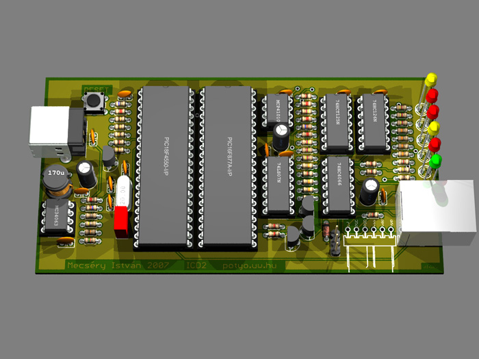
blueroomelectronics said:As said before it's much easier to build a PICkit2 clone.
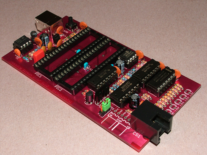
Check thisKXLU said:Hm,I think there is no resistor which hase 0.47ohm resistance.In potyo2.pdf there is R41 0.47 resistor.Can I change it to jumper(short)?