RedAlert
Member level 1
- Joined
- Oct 13, 2001
- Messages
- 38
- Helped
- 0
- Reputation
- 0
- Reaction score
- 0
- Trophy points
- 1,286
- Location
- Somewhere in Israel
- Activity points
- 176
Hi,
Can someone help me on this:
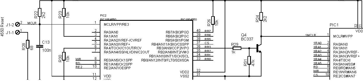
I am going to build the ICD2 clone made by PiCS(Rev B) and would like to know that after I finished assembly the Hardware, there is 2 hex file in the zip file
(http://www.icd2clone.com/w/images/a/a3/ICD2_Clone_4550_-_PiCS.zip).
Do I need both of them, and also how I upload the firmware(s) to the PICS from the computer ?
Also, after I do the previous step, should I download the OS firmware as well
(as found in MPLAB) ?
When I buy Original ICD2, does it have pre-firmware inside of it?
Can someone help me on this:
I am going to build the ICD2 clone made by PiCS(Rev B) and would like to know that after I finished assembly the Hardware, there is 2 hex file in the zip file
(http://www.icd2clone.com/w/images/a/a3/ICD2_Clone_4550_-_PiCS.zip).
Do I need both of them, and also how I upload the firmware(s) to the PICS from the computer ?
Also, after I do the previous step, should I download the OS firmware as well
(as found in MPLAB) ?
When I buy Original ICD2, does it have pre-firmware inside of it?