tucheng
Newbie level 6
I am designing a five-orders mirostrip combline filter on a 1.27mm thick substrate with a relative dielectric constant of 10.8. I let the microstrip resonators be lambda/4 long and require no capacitive loading for this filter design. There is a metal vias to ground at the end of each resonator.
Step 1: extract coupling coefficient between two resonators
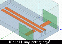
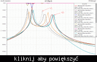
The model was established in HFSS11.0. As can be seen below, a pair of resonators is loosely coupled by the open-circuit transmission line. Then the simulation result shows double peak response as expected. But when I increased the gap distance between the two resonators, double peaks both shift to low side, which means the center frequenc decreased. I thought these two peaks would shift in opposite direction and the center frequency keep unchanged. Is my original idea wrong? If I am right, can anyone tell me why center frequency shifts as coupling between the two resonators decrease?


Step 2: extract external Q
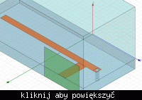
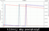
The model and the simulation result can be seen below. The same problem happened as step 1. Center frequency( where the phase of S11 changes most dramatically) shifts as tapped point varies!


Please help. Thank you in advance!
Step 1: extract coupling coefficient between two resonators
The model was established in HFSS11.0. As can be seen below, a pair of resonators is loosely coupled by the open-circuit transmission line. Then the simulation result shows double peak response as expected. But when I increased the gap distance between the two resonators, double peaks both shift to low side, which means the center frequenc decreased. I thought these two peaks would shift in opposite direction and the center frequency keep unchanged. Is my original idea wrong? If I am right, can anyone tell me why center frequency shifts as coupling between the two resonators decrease?


Step 2: extract external Q
The model and the simulation result can be seen below. The same problem happened as step 1. Center frequency( where the phase of S11 changes most dramatically) shifts as tapped point varies!


Please help. Thank you in advance!