Continue to Site

Welcome to EDAboard.com

Welcome to our site! EDAboard.com is an international Electronics Discussion Forum focused on EDA software, circuits, schematics, books, theory, papers, asic, pld, 8051, DSP, Network, RF, Analog Design, PCB, Service Manuals... and a whole lot more! To participate you need to register. Registration is free. Click here to register now.

Problem with R-2R Ladder DAC

Status
Not open for further replies.
Dominik Przyborowski say:
Use smaller resistors and external low resistance switches driving from uC.
thank,yes of course ,i have a big problem in high freq>50Khz,please help me to reduced this problem or show me how replace this circuit with other circuit.please recommend new circuit schematic for build dac circuit.
how i can calculate r2r ladder network resistor value?
Can you explain what your code is doing ? GPIO -> ODR=x ?? And how do you set the update rate in your loop for specific frequencies ?

In addition, what is your oscilloscope specs ? I cannot make out which make/ model it is.

thanks
output port value increased step by step in this loop to build a ramp signal,r2r ladder convert this fragment value to analog signal,ODR is register to write GPIO port value,frequency can be increased by increase jump step in base loop.
similar technique like NCO oscillators.my osc is frequency BW is 20MHz,Micro AZ.
 

You are seeing the limited slew rate (typically 0.5 V/µs) of LM324. Use a faster OP like TL074.

i replace LM324 with TL084 but problem not solved...
TL084 Slew rate is 13V/uS but i have a discharging signal end of ramp signal...
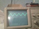
signal before op-amp at 100Khz
IMG_20140803_152929.jpg
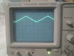
op-amp signal output:
IMG_20140803_152949.jpg
please help me
 
Last edited:

Assuming you are cycling through only 256 values (8 bits), then your update rate at 100Khz of the sawtooth implies you are outputting a 'new' data @ 100K x 256 = 25.6Mhz !! If you are cycling 10 bits, then it is even higher at >100Mhz. This is higher than your 'scopes BW and maybe causing some trouble.

Is this so ? Or are my calculations wrong ? Is your uC and code doing this ?

In addition, at this frequency, even a capacitance of 2pF will have an impedance of only 3Kohm, which is less than your r-2r ladder.

On an average breadboard implementation, chances are you have even higher parasitic capacitances.

Lastly, at the places where the ramp makes 'sharp' transitions you will see problems. These again are due to parasitic capacitances, and ALSO will be seen if your oscilloscope PROBE is not properly compensated ! What is your probes specs, and have you compensated it ?

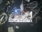
Maybe it is time for you to post a pic of your 'real' circuit board as implemented currently ?
 
The "before op amp" signal looks like you are loading the node with a big capacitance, e.g. 1:1 osciloscope probe. The OP output signal isn't plausible for a high speed OP and the circuit according to post #13. What's the actual slew rate achieved in this case? It can't be seen from the photos.
 

Assuming you are cycling through only 256 values (8 bits), then your update rate at 100Khz of the sawtooth implies you are outputting a 'new' data @ 100K x 256 = 25.6Mhz !! If you are cycling 10 bits, then it is even higher at >100Mhz. This is higher than your 'scopes BW and maybe causing some trouble.

Is this so ? Or are my calculations wrong ? Is your uC and code doing this ?
hi
thanks,your calculation have a bit wrong items,
i build 100Khz freq with 52 samples of ramp signal.
in main loop jump steps defined output freq.
in 100Khz with 52sample update rate equal ~2Mhz.
number of bit only define resolution dac.

i don't know about osc probes property specs.
probes just have a trimmer cap in circuit for tuning signal edge at higher freq.
IMG_20140803_185753.jpg
i try to make circuit on the pcb to decries parasitic capacitance.
but i have big problem with op-amp because output freq on op-amp spend big time on discharging signal and lost sharp rarmp signal.
i use a op-amp with higher slew rate but problem not solved...

- - - Updated - - -

The "before op amp" signal looks like you are loading the node with a big capacitance, e.g. 1:1 osciloscope probe. The OP output signal isn't plausible for a high speed OP and the circuit according to post #13. What's the actual slew rate achieved in this case? It can't be seen from the photos.
thanks
yes of course,dac output have a big rising time and falling time,after op-amp i have a sharped rising time and big falling time!!!
a big capacitance in my board.
i build pcb of circuit and try it again.
real circuit is matched by schematic.
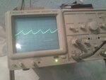
in this picture actual slew rate is showed:
IMG_20140803_190917.jpg
osc Time/Dive Set on 2us.
thanks for attention
 

in 100Khz with 52sample update rate equal ~2Mhz.

Sounds as a quite daring specification of design for assemble on a wired breadboard employing relatively standard components. Would be recommended start thinking about draw a compact PCB layout for that.

Furthermore, protoboards have inner tracks along its entire lengh which can act as real antennas, therefore becoming not a suitable environment for such tests.


+++
 
Status
Not open for further replies.

Similar threads

Part and Inventory Search

Welcome to EDABoard.com

Sponsor

Back
Top