Continue to Site

Welcome to EDAboard.com

Welcome to our site! EDAboard.com is an international Electronics Discussion Forum focused on EDA software, circuits, schematics, books, theory, papers, asic, pld, 8051, DSP, Network, RF, Analog Design, PCB, Service Manuals... and a whole lot more! To participate you need to register. Registration is free. Click here to register now.

Problem with R-2R Ladder DAC

Status
Not open for further replies.

Persian_Men

Junior Member level 1
Joined
Nov 29, 2008
Messages
18
Helped
5
Reputation
10
Reaction score
4
Trophy points
1,283
Activity points
1,455
Hi guys.
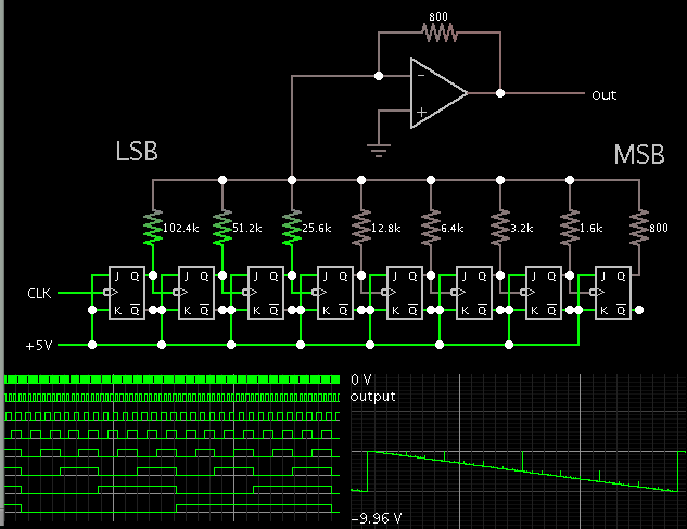
i design r-2r ladder dac semilar this schematic for design signal generator.
i use ARM GPIO port to connect to r-2r dac.
i design 10bit r-2r ladder network.
when i want to build ramp signal output is not equal ramp signal
17th0ls9ahwb2r0ek7bb.jpg
ramp code is:

Code C - [expand]
1
2
3
4
for (x=0;x<1023;x++)
{
GPIOA->ODR=x;
}


when i was use 8bit resolution i see a complate ramp signal:
rwsn2vke6l09qb6en4x1.jpg
anybody can help me?
 

Hi,

it seems like interchanged bits.

or your r2r ladder is not correct.

check if the two MSBs have the right R value and 2R value.


Klaus
 
Hi,

it seems like interchanged bits.

or your r2r ladder is not correct.

check if the two MSBs have the right R value and 2R value.


Klaus
hi
thanks KlausST
i replace resistor with r=10k,and 2r=22k and get better ramp signal.
IMG_20140802_181108.jpg
in old circuit r=4.7K and 2r=10K.
how i can get better smooths signal?
how i can calculate R value's?
V high=3.3V in arm GPIO.
thanks again
 

Small deviations from the mean of the resistors may result in abrupt transitions, especially those resistors nearest the beginning of the network.

By the way, what is the accuracy of these resistors ?


+++
 
For 10bits the accuracy of resistors should be 0.01% and switch resistance (or output resistance in your driver) should be also 1000 times smaller than R value.
 

Hi
thanks for answer,
the accuracy of resistor is gold or 5%
please help me to chose better resistor value to reduce deviations of signal.
replace resistor's with 1% accuracy can help me to reduce deviations?
how i can calculate better resistor's value?
thanks alot

- - - Updated - - -

can i increase resolution up to 12bit or 14bit for use higher accuracy resistor's?
 

i replace resistor with r=10k,and 2r=22k and get better ramp signal.

This surelly tends to degenerate the ramp shape.

can i increase resolution up to 12bit or 14bit for use higher accuracy resistor's?

I´m not sure if you will easily find resistors having higher precision than 0,1%.


+++
 

why "This surelly tends to degenerate the ramp shape."??
i can get some resistor with accuracy 1% and replace it.
how i calculate R value?
 

can i increase resolution up to 12bit or 14bit for use higher accuracy resistor's?

For higher resolution You should use external very low resistance switches and segmented DAC architecture (MSBs should be unary while LSBs binary switching) or use some IC DAC.
 
You should employ the doubled resistance value to each subsequent component, therefore replacing resistor with r=10k,and 2r=22k would add an error near to 10% from 20K desired value.


+++
 

why "This surelly tends to degenerate the ramp shape."??
i can get some resistor with accuracy 1% and replace it.
how i calculate R value?

- - - Updated - - -

thanks.
i increase step of counter and get higher freq.
in this picture freq above ~85Khz but signal shape is not enough quality...
IMG_20140802_192315.jpg
i now replace 22k with double 10k with same accuracy and couple r=10k and 2r=20k and replay again/

- - - Updated - - -

i replace 22k with double 10k and get this result:
IMG_20140802_194040.jpg
freq ~ 5khz
and on freq above 88Khz i get this
IMG_20140802_194118.jpg

i can't use dac chip,how i can increase signal smooth?

- - - Updated - - -

please help me to use circuit better than r-2r ladder network.
thanks
 

The complains about bad high frequency waveform are meaningless without a schematic. You claimed to show it in post #1 but you never didn't.
 
The complains about bad high frequency waveform are meaningless without a schematic. You claimed to show it in post #1 but you never didn't.

thanks
schematic:
Untitled.gif
please help me
 
Hi,

R-2R means one resistor has a known value (R = 10k) and the other resistor should have 2x the resistance 2R = 2 x R = 2 x 10K = 20k

22k is not 20k therfore the distortion.

use 10k and 20k and distortion is away.

Klaus
 
There is missing a capacitor near to R21 for damp the edges during input transitions. I presume somewhat near to 100nF could suffice.

Anyway, this have no relation to distortion shown on the last picture.
Check if the OpAmp assembled on tested circuit really is the same drawn in schematic.


+++
 
please help me to use circuit better than r-2r ladder network.
thanks

One alternative is the binary-weighted resistor network.


The range of values is chosen so no device has to provide more than 13 mA (or whatever is the maximum load recommended for your device).
 
You might want, for a one-off, to make your resistors each a
combination of a large base (say, 9900 and 19800) and a small
select-resistor (0 - 100, 0-200) and by good quality 4-probe
measurements you could greatly increase the individual
accuracy. This (trimming) was essential to old-school DACs
before the days wwhen you could integrate a ton of CMOS
switches and OTP elements, or do auto-cal. You'd want an
assortment of the low value resistors, in increments small
enough to give you the desired net accuracy.

Matching would also be improved if your CMOS outputs'
on resistance / drive strength was weighted the same as
the resistors, if you go to a parallel weighted network.
Otherwise there will be an increasing error as you go up
toward MSB.
 
R-2R ladder is also a binary weighted network.
The problem with dynamic response for higher frequencies causing probably from time constant at the output node of a ladder - it seems to be around 2us and the current capability of microcontroler.

Use smaller resistors and external low resistance switches driving from uC.
 
i check op-amp supply voltage and see it's not regular dc signal,i use cap to dump noise on power supply lines,and try again to test code,i check schematic with test circuit and all thing is same of schematic.
figure 1:run ramp in 5Khz
5K.jpg
Code:
	while(1)
	{
		for (x=0;x<1024;x+=1)
			GPIOA->ODR=(uint16_t)x;
	}
figure 2:run ramp in 50Khz
50K.jpg

Code:
	while(1)
	{
		for (x=0;x<1024;x+=10)
			GPIOA->ODR=(uint16_t)x;
	}
figure 3:run ramp in 100Khz
100K.jpg

Code:
	while(1)
	{
		for (x=0;x<1024;x+=20)
			GPIOA->ODR=(uint16_t)x;
	}
why after ramp signal i have a similar discharging signal??
 
Last edited:

Can you explain what your code is doing ? GPIO -> ODR=x ?? And how do you set the update rate in your loop for specific frequencies ?

In addition, what is your oscilloscope specs ? I cannot make out which make/ model it is.
 
Status
Not open for further replies.

Similar threads

Part and Inventory Search

Welcome to EDABoard.com

Sponsor

Back
Top