Continue to Site

Welcome to EDAboard.com

Welcome to our site! EDAboard.com is an international Electronics Discussion Forum focused on EDA software, circuits, schematics, books, theory, papers, asic, pld, 8051, DSP, Network, RF, Analog Design, PCB, Service Manuals... and a whole lot more! To participate you need to register. Registration is free. Click here to register now.

[PIC] Problem in RTC with PIC16F877A controller

Status
Not open for further replies.

Logu KS

Member level 2
Joined
Jul 19, 2014
Messages
43
Helped
0
Reputation
0
Reaction score
0
Trophy points
6
Location
Chennai
Activity points
372
I interfaced a RTC with PIC through I2C. After setting the time and date it runs properly but after 2 or 3 hours the time gets lagging/leading.
 

I interfaced a RTC with PIC through I2C. After setting the time and date it runs properly but after 2 or 3 hours the time gets lagging/leading.
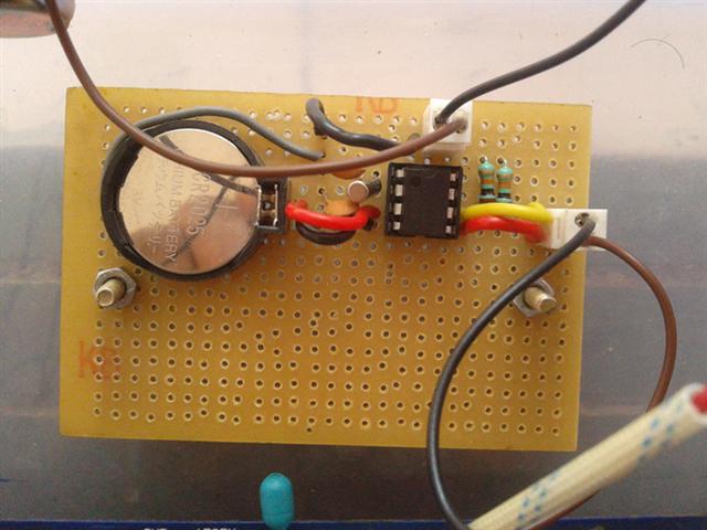
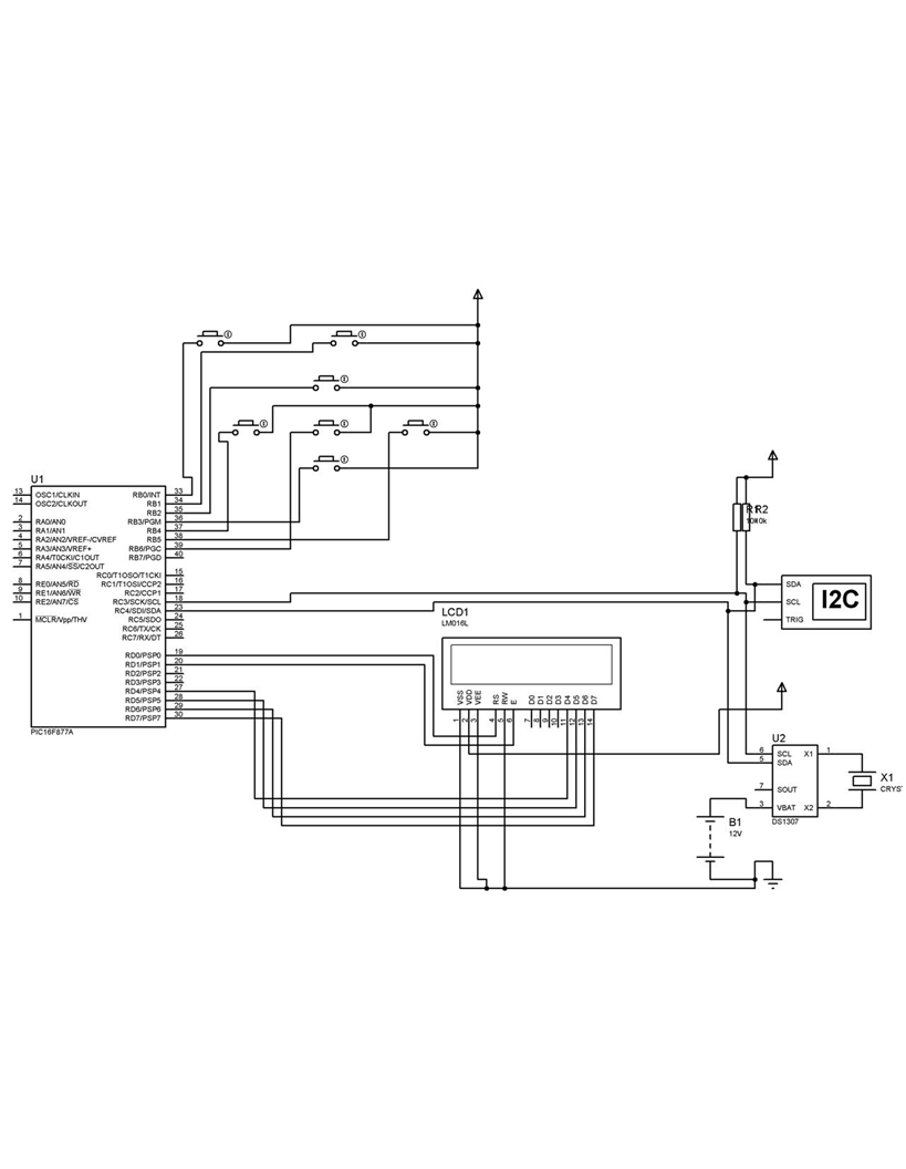
what oscillator are you using for the RTC?
could you post a circuit?
 

32.678KHz crystall oscillator

- - - Updated - - -

crystal oscilator.jpg
 

Attachments

  • crystal oscilator.jpg
    crystal oscilator.jpg
    90 KB · Views: 132

the crystal should be a 32.768kHz your post said 32.678KHz but I guess that was a typo

the device is sensitive to crystal load capacitance which should be about 12.5pF (I seem to remember having to change some crystals due to this causing problems)

however, I would not expect is to drift significantly within a few hours - how much is your drift?

are you getting significant temperature changes?
 

Iam getting delay in seconds approximately 10 seconds/day.
 

10 seconds per day sounds like a frequency error in the RTC oscillator. For some reason the crystal frequency is very slightly low. I would guess either the crystal is out of tolerance or you have not carefully followed the manufacturers board layout and the extra inductance and capacitance at the crystal connections is pulling the frequency.

Brian.
 

I didnt used any capacitor for the crystal connection.
I found one post in engineers garage in that they connected 12.5pf capacitors to the crystal oscillator.


Looking at your schematic I presume that the power supply to the RTC is 5v and the backup is 3v (not 12 as shown)?

You don't need external load capacitors but you have to make sure that the load capacitance of your crystal is 12.5pF - what is the load of your crystal. Where did you get your crystal from, those on E-bay are low quality and have quite high tolerances i.e. ppm.

If you used a 12.5pF crystal with an accuracy of 40ppm, you will have an error of about 4-5 sec a day. If the load capacitance of the crystal is different you can easily get to 10 sec a day.
 

Also, if you are using 'Veroboard' or similar board with copper strips, cut them just beyond the crystal so the tracks are as short as possible.

Brian.
 

Status
Not open for further replies.

Similar threads

Part and Inventory Search

Welcome to EDABoard.com

Sponsor

Back
Top