ahmeddeia
Member level 2
Alsalam alikom
h r u everybody?? i hope u r all fine
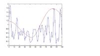
well i have a certain problem concerning channel interpolation,well i use pilots to estimate the channel frequency response then use the results to interpolate them
but the interpolated figure is far away from the real one (which is plotted in red)
please check out this figure
can any one pls help me
---------- Post added at 23:54 ---------- Previous post was at 22:23 ----------
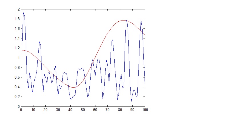
i nearly figure it out
i didn't use awgn channel as i only used rayleih channel without adding noise
the figure become more reasonable but not a satisfying one
so any one can help what to use in order to have better channel interpolation??
i used interp1 in matlab,linear interpolation as time interpolation ,and spline one as frequency interpolation
h r u everybody?? i hope u r all fine
well i have a certain problem concerning channel interpolation,well i use pilots to estimate the channel frequency response then use the results to interpolate them
but the interpolated figure is far away from the real one (which is plotted in red)
please check out this figure
can any one pls help me
---------- Post added at 23:54 ---------- Previous post was at 22:23 ----------
i nearly figure it out
i didn't use awgn channel as i only used rayleih channel without adding noise
the figure become more reasonable but not a satisfying one
so any one can help what to use in order to have better channel interpolation??
i used interp1 in matlab,linear interpolation as time interpolation ,and spline one as frequency interpolation