cnhoff
Newbie level 4
Probem with Ports/boundaries in CST MWS
Hello,
i am trying to simulate a suspended stripline filter actually, but as i am new to CST i have some basic problems.
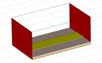
I tried to simulate Microstrip line (Ro4350 lossy 50 Ohm line made of Gold). I dont have bottomside metallization, as i am using electric walls on all sides. Now i first only set one port at the beginning of the line (substrate edge), the waveguide end was obviously shorted by the electric boundary when i examined the smith chart. Phase-shift was believable also.
When i set a second port at the other end of the line, i have non-believable results. S11 is lower than -60 dB and S21 neglectably low and Smith Chart is only one single matched dot. When i considerably change MS line width, results basically stay the same, although port impedance changes correctly...
I really don't know whats happening there i just do not get resonably results with 2 ports. Btw i am using the planar filter preset.
Can anyone help please?!
Chris
Hello,
i am trying to simulate a suspended stripline filter actually, but as i am new to CST i have some basic problems.
I tried to simulate Microstrip line (Ro4350 lossy 50 Ohm line made of Gold). I dont have bottomside metallization, as i am using electric walls on all sides. Now i first only set one port at the beginning of the line (substrate edge), the waveguide end was obviously shorted by the electric boundary when i examined the smith chart. Phase-shift was believable also.
When i set a second port at the other end of the line, i have non-believable results. S11 is lower than -60 dB and S21 neglectably low and Smith Chart is only one single matched dot. When i considerably change MS line width, results basically stay the same, although port impedance changes correctly...
I really don't know whats happening there i just do not get resonably results with 2 ports. Btw i am using the planar filter preset.

Can anyone help please?!
Chris
Last edited: