Continue to Site

Welcome to EDAboard.com

Welcome to our site! EDAboard.com is an international Electronics Discussion Forum focused on EDA software, circuits, schematics, books, theory, papers, asic, pld, 8051, DSP, Network, RF, Analog Design, PCB, Service Manuals... and a whole lot more! To participate you need to register. Registration is free. Click here to register now.

Power supply overvoltage

Status
Not open for further replies.

kiks

Member level 1
Joined
Jun 1, 2004
Messages
35
Helped
3
Reputation
6
Reaction score
3
Trophy points
1,288
Activity points
349
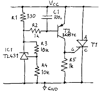
What is the best way to protect circuits from overvoltage. I recently had a case where a 5vdc switching power supply failed and went up to 9vdc. This fried the circuit boards that it supplied. MOVs might be a bit slow ,I think. Any ideas, circuits etc will be appreciated. The circuits boards are supplied with 24vdc and 5vdc from seperate switching power supplies.

Thanks in advance

:smile:
 

Use a TL431 or Zener to activate an SCR connected across power rail and ground. A.k.a. crowbar circuit :)

crowbar2.png


Adjust R3 and R4 to set the trigger voltage, formula for calculating TL431 voltage is: 2.5*(1+ (R3/R4))

It's easy to implement because the circuit lives on the secondary side and runs off the output voltage, first sign of trouble the crowbar is dropped across the power rail and either over current detection trips, fuse blows or sparks fly BUT at least the load isn't damaged!
 
Last edited:

Thank you very much for the quick response. So as the circuit stands, using the formula and the given values for R3 & R4, the trigger value is 5v right? Next question, what is the safe/max voltage for 5v digital/microcontroller circuits without causing damage?
 

So you're talking about overvoltage on the output of a regulator, not an input?

The appropriate solution depends on knowing the origin of the overvoltage. If it's due to some kind of transient overshoot on the supply regulator, then modifying its control loop is an easy solution. Methods like crowbars should only be considered only when absolutely necessary, since their operation usually protects certain parts of the circuit while shifting the hazard to other parts. For example a crowbar might prevent a supply voltage overshoot, but in the process of clamping the supply voltage it may destroy the regulator for the supply, unless you use some sort of fuse.
 

Correct, two 10K resistors makes 5V - 2.5*(1+(10000/10000))=5V

As for maximum safe voltage I am not sure but the ATX V2.2 standard specifies the following tolerances for it's various power rails:

+3.3VDC ± 5% +3.135 VDC +3.465 VDC
--> +5VDC ± 5% +4.750 VDC +5.250 VDC <--
+5VSB ± 5% +4.750 VDC +5.250 VDC
-5VDC ± 10% -4.500 VDC -5.500 VDC
+12VDC ± 5% +11.400 VDC +12.600 VDC
-12VDC ± 10% -10.800 VDC - 13.200 VDC

If it's good enough for the ATX specification, it might be good enough for you. So for 5.25V that gives a 10K and a 9.1K resistor.

Also note that the SCR in the circuit can be removed and replaced with an Optocoupler and some circuitry could be added to the primary side to blank the PWM output using the Phototransistor.
 
Last edited:

Thank you all for your replies. The over voltage was on the output of a switching power supply which failed. I have seen and worked with crowbar circuits, but have found them to be very destructive - although they do a good job of protecting the circuit supplied. I have worked with MOVs as well. They seem to be better suited to mains voltages, in fact they work very well on mains AC supplies.
 

you can connect the load through a series pass FET controlled by a TL431 which is fast and good
 

Status
Not open for further replies.

Similar threads

Part and Inventory Search

Welcome to EDABoard.com

Sponsor

Back
Top