w_bwr
Member level 3
- Joined
- Feb 4, 2010
- Messages
- 66
- Helped
- 0
- Reputation
- 0
- Reaction score
- 0
- Trophy points
- 1,286
- Location
- Karachi, Pakistan
- Activity points
- 1,810
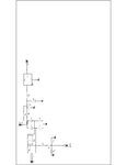
I have a schematic. (image attached)

Voltage after R7 (150k/2W) drops to 150 v and after diode i should get (150/2-0.7 = 74.3 v) but i only get 10 volts. How does that happens.
After Diode, voltage is to be fed to a controller to compare the AC Voltage.
Purpose of the circuit is to compare the incoming AC Voltage if greater or lesser the controller will not activate the relay for the sake of appliance safety, if appropriate (180 to 230) than the controller will activate the relay.