Continue to Site

Welcome to EDAboard.com

Welcome to our site! EDAboard.com is an international Electronics Discussion Forum focused on EDA software, circuits, schematics, books, theory, papers, asic, pld, 8051, DSP, Network, RF, Analog Design, PCB, Service Manuals... and a whole lot more! To participate you need to register. Registration is free. Click here to register now.

Power-out Alert and 555 Timer

Status
Not open for further replies.

mcbbcn

Newbie level 4
Joined
Dec 23, 2010
Messages
7
Helped
0
Reputation
0
Reaction score
0
Trophy points
1,281
Activity points
1,354
Hi,

I would like to use a Power-Out Alert device (**broken link removed**) to detect a power outage and actuate/trigger a relay. Basically, I need to convert the continuous signal of the power-out sensor into one single-shot or single pulse signal.

The power-out alert device has a cable with two wires (a common wire and a N.O. wire) and when the power goes out it trips both wires for as long as the condition exist. Similar to safety lights with a motion sensor, when the motion sensor detects motion, it triggers a continuous alarm signal and the lights turn on.

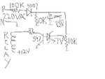
I've read about the 555 monostable circuit but unfortunately my knowledge about electronics is limited so I'm not sure this is what I need and how to do it.

I was wondering if a kind soul could take a look at the above link and tell me if I'm going down the right path with a 555 monostable circuit.

Thanks for your help,

Miquel Casas
Portland, OR
 

i have attached acircuit,that may help you
 

Attachments

  • surjeet.JPG
    surjeet.JPG
    20.6 KB · Views: 139
  • Like
Reactions: mcbbcn

    mcbbcn

    Points: 2
    Helpful Answer Positive Rating
u can get easily monostable 555 ckt just google .in 555 monostable pin2 is active low when triggered out pin 3 can connect to led or relay using suitable interface and the time upto which pin 3 is high controlled by rc network
 
  • Like
Reactions: mcbbcn

    mcbbcn

    Points: 2
    Helpful Answer Positive Rating
Last edited:
  • Like
Reactions: mcbbcn

    mcbbcn

    Points: 2
    Helpful Answer Positive Rating
Thank you all. This is a great forum.

Best regards to all of you.

M.
 

Hi all again,

I have one more question. The Power-Out Alert device has a cable for Common and a cable for NO which they get tripped where there is no power.

When I look at the 555 pins, I think that the Common wire will go to the GND pin of the 555 device and the NO wire will go to the Trigger pin of the 555 device. Am I right or wrong?

Thank you again and I apologyze for not coming up with all the questions at the same time.

Best regards,

Miquel Casas
Portland, OR
 

Yes, sort of. You need to feed the signal into the 555 through a capacitor as shown in the second link I gave you.
 
  • Like
Reactions: mcbbcn

    mcbbcn

    Points: 2
    Helpful Answer Positive Rating
Yes, sort of. You need to feed the signal into the 555 through a capacitor as shown in the second link I gave you.

Wow! I was completely off. Looking at your diagram, you are feeding one end of the switch (AKA N.O.) to pin 2 TRG, I guessed right on that one but you are feeding the other end (in my case Common wire) to C1 which it is connected to pin 1, pin 5 and pin 6, right?

Once I get the high-output from pin 3, how do I feed it to my two-contact relay? I was assuming pin 3 (output) will be in one of the contacts of the relay but what do you feed to the other relay contact?

By the way, I noticed on your diagram that it says that SW1 goes momentarily to low, but in my case, it is not momentary thing, it will stay in low (AKA tripping NO and Common) for as long as the condition exist. It's like a motion sensor in safety light...the motion sensor will keep giving the signal for as long as the motion exist but I only need one pulse out to turn on the lights, so to speak...in my case, it's not lights, it's a relay.

Thanks for your help. This is immensely helpful.

M.
 

Wow! I was completely off. Looking at your diagram, you are feeding one end of the switch (AKA N.O.) to pin 2 TRG, I guessed right on that one but you are feeding the other end (in my case Common wire) to C1 which it is connected to pin 1, pin 5 and pin 6, right?

Once I get the high-output from pin 3, how do I feed it to my two-contact relay? I was assuming pin 3 (output) will be in one of the contacts of the relay but what do you feed to the other relay contact?

By the way, I noticed on your diagram that it says that SW1 goes momentarily to low, but in my case, it is not momentary thing, it will stay in low (AKA tripping NO and Common) for as long as the condition exist. It's like a motion sensor in safety light...the motion sensor will keep giving the signal for as long as the motion exist but I only need one pulse out to turn on the lights, so to speak...in my case, it's not lights, it's a relay.

? I don't think I know what you're talking about. You have a device (Power-Out Alert) that has a relay built into it. I thought you wanted to drive something that needed a momentary pulse, but it sounds like the device will do what you want by itself. What are you trying to do? I need more specific details as to why you need a pulse instead of the continuous connection of the relay contacts in your device.
 

I'm sorry if it's confusing. It's totally my fault.

You are correct, I have a device (Power-out-alert) that detects when power is out. The device has two-wires coming out to connect to an alarm, or relay or whatever...One of the wires is called common and the other wire is called NO. When the power goes out, the two-wires get a continuous pulse.

This is actually for the roof of a telescope observatory. The roof of the observatory can be openned and closed with a door-garage motor. The door garage motor has a digital panel with a switch to open and close, and this panel has two metal contacts with two wires that goes from the panel to the garage door motor. If you momentarely trip the two contacts behind the digital panel for less than a second, the garage door motor thinks that you just pulsed the button to close the roof and it closes the roof. Hopefully, all of these details are not going to make it more confusing.

So, I want to plug the power-out alert device to an outlet and then take the common wire and the NO wire that comes out of the power-out alert device and connect them to the two contacts of the garage door digital panel. The problem is that the power-out alert device will not produce a momentary pulse but it will produce a continuous pulse once the power-goes out and actually, a continuous pulse will be not be accepted by the two contacts behind the garage door digital panel. But, if I could convert the continuous pulse that comes out of the power-out alert device (through the common and NO wires) into one single pulse of less than a second, it will actually close the roof of my observatory in the event of a power outage.

Please, let me know if this helping or making it more confusing.

Also I have another sensor that does a similar thing. It's a rain-detector and it does the same, once it detects water, it will send a continuous signal through the common wire and the NO wire of the rain detector for as long as it detects water, and then I need a way to take this continuous signal and convert it into a single-pulse that I can send to the two contacts behind the digital panel of the door garage and close the roof.

I hope it helps. Thanks for your help.

M.
 

That makes a lot more sense now. The information I gave for using a 555 is correct for this application but the circuit topologies that I've given you are general and not specific to your use. You seem to be under the impression that common and N. O. are separate outputs of some kind when in fact they are just the two contacts of a SPST relay.

Your description raises another more fundamental question though. If the power is out, what's the door motor running on? You have some kind of battery powered unit I hope, otherwise the control circuits are moot.

I'll try to draw you a basic schematic for your situation later.
 
  • Like
Reactions: mcbbcn

    mcbbcn

    Points: 2
    Helpful Answer Positive Rating
Thank you. It makes sense what you are saying about being part of the same SPST relay.

And yes, you are correct, the motor is running on backup battery, so that is not an issue.

Thanks for taking the time to draw the schematic. I really appreciate it and I'll be happy to send you a paypal fee for your time and effort.

Best regards,

M.
 

Status
Not open for further replies.

Part and Inventory Search

Welcome to EDABoard.com

Sponsor

Back
Top