Continue to Site

Welcome to EDAboard.com

Welcome to our site! EDAboard.com is an international Electronics Discussion Forum focused on EDA software, circuits, schematics, books, theory, papers, asic, pld, 8051, DSP, Network, RF, Analog Design, PCB, Service Manuals... and a whole lot more! To participate you need to register. Registration is free. Click here to register now.

PNP as a clamp

Status
Not open for further replies.

tronicman

Junior Member level 1
Joined
May 22, 2016
Messages
15
Helped
0
Reputation
0
Reaction score
0
Trophy points
1
Activity points
100
hello guys,
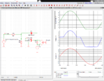
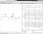
i just want a piece of help, this PNP is used as a clamp and im strugling to calculate or to determine the clamp voltage at which the Vout will be clamped ,
thnx for helping me,
PNP clamp.png
 

Silcon transistors have a typical BE reverse breakdown voltage of 7V. The transistor model in post #4 still shows no reverse breakdown at 14V, very unrealistic.
 

Silcon transistors have a typical BE reverse breakdown voltage of 7V. The transistor model in post #4 still shows no reverse breakdown at 14V, very unrealistic.
Excellent point, so I strapped a 4.7V zener to simulate the Vebo rating (datasheet I looked at
was 5.0 V) problem. Clearly spice model incomplete. As you can see clamp results very poor.


1607037898340.png


If I raise input R to 10 K -

1607037798981.png


Regards, Dana.
 

Attachments

  • 1607037414807.png
    1607037414807.png
    122.1 KB · Views: 133
  • 1607037751749.png
    1607037751749.png
    122.1 KB · Views: 150
Last edited:

Status
Not open for further replies.

Similar threads

Part and Inventory Search

Welcome to EDABoard.com

Sponsor

Back
Top