Gayathri Jeyaram
Junior Member level 1
I am currently doing a project that involves a PLL design using simulink.
The specs are as mentioned. Input frequency: 70MHZ, Loop Bandwidth: 1KHZ.
Could anyone tell me how I can find the values for pd, vco, Loop filter gains (kd, kf and kv) and R1 C1 C2 parameters of the 2nd order lead lag loop filter ? A list of formula would be nice. I have been reading a lot of pdfs. I find them hard to comprehend, each pdf is more complex than the other or maybe I am just using my patience.
My simulink model includes the following:
Input sine wave used is a reference sine block.
PD used is a multiplier.
Loop filter used is a lead-lag filter of order 2.
VCO used is a continuous time VCO.
Scope to view the waves from VCO and Input.
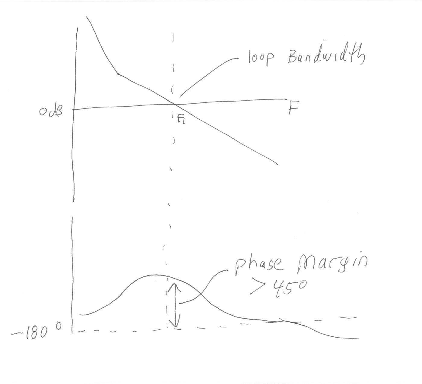
Then how to analyse the output using a Scope ? How to validate my output in terms of loop bandwidth ?
The specs are as mentioned. Input frequency: 70MHZ, Loop Bandwidth: 1KHZ.
Could anyone tell me how I can find the values for pd, vco, Loop filter gains (kd, kf and kv) and R1 C1 C2 parameters of the 2nd order lead lag loop filter ? A list of formula would be nice. I have been reading a lot of pdfs. I find them hard to comprehend, each pdf is more complex than the other or maybe I am just using my patience.
My simulink model includes the following:
Input sine wave used is a reference sine block.
PD used is a multiplier.
Loop filter used is a lead-lag filter of order 2.
VCO used is a continuous time VCO.
Scope to view the waves from VCO and Input.
Then how to analyse the output using a Scope ? How to validate my output in terms of loop bandwidth ?