Seems as transistors are not well biased.
+++
+++
Follow along with the video below to see how to install our site as a web app on your home screen.
Note: This feature may not be available in some browsers.
What are bubles?
Can you show the circuit in the book?
What seems to be the problem? Have you breadboarded the circuit? What do you mean by drawing...?
PS: You can get rid of R1, it is not needed, just connect switch to ground
I think the problem is that you didn't fully understand the operation of the circuit. (I must confess that I also didn't realize the built-in problem at first sight).
By design, you get 9.9V across the load resistor when the transistor is "on" and still 9.3 V for Q1 and Q2 when they are "off". Only the voltage at the Q3 load resistor drops to zero in off-state. This happens because the base-emitter voltage of the succeeding stage can't rise above 0.7 V.
To get a clear off-state for Q1 and Q2, you need to add base series resistors of e.g. 10 or 20 K.
fvm has been right all along. For the circuit to work, you will need some base bias resistors, the value of each base resistor must be atleast 10 times the load resistor
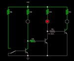
Yes, and it's expected to work as is. The curious thing is that michael 1978 is seeing three "bubbles" (lamps? meters?) somewhere, but we don't know in which circuit. Neither we know which circuit produced the strange ampere readings in post #20. The "book" circuit in post #22 is given without any resistor values.Circuit in book only has ONE lamp.
This is the circuit from the book.yes but i read one book, he put three bubles...

circuit in book only has one lamp.
This is the circuit from the book.
I don't see three bubles.
What do you mean by "bubles"?
@FvM: I think this is hopeless, the OP's command of English is too poor. Maybe if he told us what his home language is, somebody could explain to him in his own language.
LEDs ON OFF ON OFF.......PositionA
LEDs OFF ON OFF ON.......PositionB
https://obrazki.elektroda.pl/6181116400_1388210564.png
interesting... But theres a lot of wasted power too turn off leds
Hello dude,May i know reason for how power loss is more
because the current through each transistor's collector is always the same when it is on or off.