Continue to Site

Welcome to EDAboard.com

Welcome to our site! EDAboard.com is an international Electronics Discussion Forum focused on EDA software, circuits, schematics, books, theory, papers, asic, pld, 8051, DSP, Network, RF, Analog Design, PCB, Service Manuals... and a whole lot more! To participate you need to register. Registration is free. Click here to register now.

Please help about transistor as switch

Status
Not open for further replies.
please can you help, explain me in easy way this circuit
https://obrazki.elektroda.pl/2237673700_1387888073.jpg

normal must be
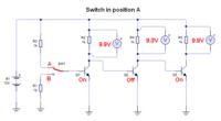
swith in position A
q1 on
q2 off
q3 on

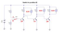
switch in position B
q1 off
q2 on
q3 off


When switch of q1 connected to ground, q1 could not be work so 9.20 voltage sufficient to start q2.
when q2 is working q3 won't get sufficient voltage to its base to switch ON. so, it will be switched OFF.

but when q1 connected to battery it will work as switch and at that time q2 won't get sufficient voltage at its base to on. so, it will goes off and due to this 9.98v goes to base of q3 so, it will switched ON.
 

You can perform this analysis yourself, just deducing that each transistor Q invert signal from Basis to Collector.

It means that 10v placed at any Basis, produces 0v at its collector.
Due Basis of next transistors are connected to previous transistor Collector, signal will be inverted again and ahead.

In other words, this circuit performs a cascaded inverter.


michael 1978,
Please, don´t ask for same subject on different threads
.


+++
 

THNX FOR REPLY BUT HOW CAN I MAKE THE CIRCUIT TO WORK

swith in position A
q1 on
q2 off
q3 on

switch in position B
q1 off
q2 on
q3 off
THNX
 

THNX FOR REPLY BUT HOW CAN I MAKE THE CIRCUIT TO WORK

swith in position A
q1 on
q2 off
q3 on

switch in position B
q1 off
q2 on
q3 off
THNX

The circuit should work as intended unless you have incorrectly wired them. Double check your wiring
 

what logic you presumed to define "circuit working" in terms of terminology on/off you mentioned ?


+++

yes on off

- - - Updated - - -

The circuit should work as intended unless you have incorrectly wired them. Double check your wiring


CAN YOU HELP PLEASE HOW TO WIRE OF IF YOU HAVE TIME TO DRAW ON CIRCUIT ON OFF ON, OFF ON OFF? THREE TRANSISTORS
 

What seems to be the problem? Have you breadboarded the circuit? What do you mean by drawing...?

PS: You can get rid of R1, it is not needed, just connect switch to ground
 

Is this what you want?


YS THIS IS WHAT I WANT BUT HOW I HAVE TO CONNECT TO WORK IN YOU CIRCUIT?, i see in book they work like this but with the lamp, so is like you in circuit they work , on off on, off on off, so when i simulate they work on on on, and on on off WHY? how i have to work? thnx for reply
 

I think the problem is that you didn't fully understand the operation of the circuit. (I must confess that I also didn't realize the built-in problem at first sight).

By design, you get 9.9V across the load resistor when the transistor is "on" and still 9.3 V for Q1 and Q2 when they are "off". Only the voltage at the Q3 load resistor drops to zero in off-state. This happens because the base-emitter voltage of the succeeding stage can't rise above 0.7 V.

To get a clear off-state for Q1 and Q2, you need to add base series resistors of e.g. 10 or 20 K.
 

when i simulate they work on on on, and on on off
Are you sure?

In the picture you showed, the transistors are off on off.

If that picture is from your simulation, then it is working correctly.

To see if a transistor is on, probe the current flow at it's collecter.
 

so i have to add resistor in base? like this he doesnt work?

- - - Updated - - -

I think the problem is that you didn't fully understand the operation of the circuit. (I must confess that I also didn't realize the built-in problem at first sight).

By design, you get 9.9V across the load resistor when the transistor is "on" and still 9.3 V for Q1 and Q2 when they are "off". Only the voltage at the Q3 load resistor drops to zero in off-state. This happens because the base-emitter voltage of the succeeding stage can't rise above 0.7 V.

To get a clear off-state for Q1 and Q2, you need to add base series resistors of e.g. 10 or 20 K.

so i have to add resistor in base? he doesnt work like this
 

so when i simulate they work on on on, and on on off WHY? how i have to work? thnx for reply

This could never be! Is this some kind of a joke? What kind of simulation software are you using? Forget about the other 2 transistor, just simulate one. See if you can manage to get it to turn on/off!
 

This could never be! Is this some kind of a joke? What kind of simulation software are you using? Forget about the other 2 transistor, just simulate one. See if you can manage to get it to turn on/off!
i use circuit wizard student version,

- - - Updated - - -

No.

Measure the current in the transistor collectors
there is no current on transitor 1 , there is current on transitor 2, there is no current on transistor 3 when switch is in position B so off on off in position b on off onn current
 

Status
Not open for further replies.

Similar threads

Part and Inventory Search

Welcome to EDABoard.com

Sponsor

Back
Top