Continue to Site

Welcome to EDAboard.com

Welcome to our site! EDAboard.com is an international Electronics Discussion Forum focused on EDA software, circuits, schematics, books, theory, papers, asic, pld, 8051, DSP, Network, RF, Analog Design, PCB, Service Manuals... and a whole lot more! To participate you need to register. Registration is free. Click here to register now.

[PIC] PICkit(tm) 1 FLASH Starter Kit- HI TECH C language

Status
Not open for further replies.

anderotegimendia

Newbie level 4
Joined
Feb 3, 2014
Messages
7
Helped
0
Reputation
0
Reaction score
0
Trophy points
1
Activity points
121
Hi:

I bought PICkit™ 1 FLASH Starter Kit (Pic12F675) and after dominating Assembly language I decided to do the same with C language.

I have used MPLAB and I put HI TECH software in it as well

The thing is that I have read manuals and watch videos and I have not been able to make it work at all with HI TECH C language. I have just been trying to turn on a led but It is impossible.

I have written this program:


Code C - [expand]
1
2
3
4
5
6
7
8
9
10
11
12
13
14
15
16
17
18
19
20
21
#include <htc.h>
#include <pic.h>
__CONFIG(MCLRE_OFF & CP_OFF & CPD_OFF & BOREN_OFF & WDTE_OFF & PWRTE_ON & FOSC_INTRCIO);
#define _XTAL_FREQ 400000
 
void main()
{
   ANSEL = 0;       // Set ports as digital I/O, not analog input
   ADCON0 = 0;      // Shut off the A/D Converter
   CMCON = 7;       // Shut off the Comparator
   VRCON = 0;       // Shut off the Voltage Reference
   GPIO = 0;        // Initializes GPIO with zero
   TRISIO= 0b001000;
 
   while(1)
   {
      GPIO= 0b010000;
 
   }
 
}


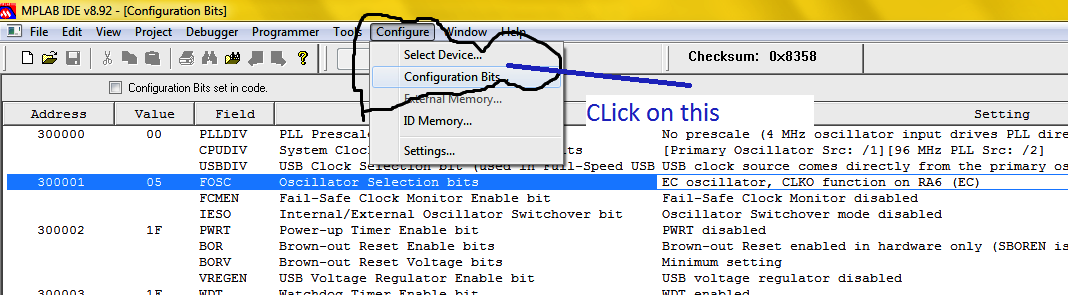
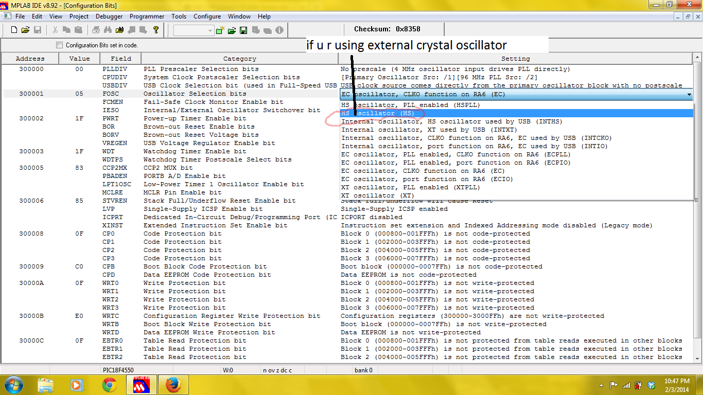
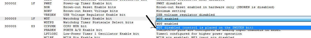
I have configured bits and I think it is ok. When I compile/build it there is no error and it says that it has been built successfully but when I program the microchip though, nothing works, nothing comes on. I don't know what I am doing wrong but I am bit desperate.

I would appreciate if you gave a reply

Looking forward to hearing from you

Thanks
 
Last edited by a moderator:

Have you selected the correct device, PIC12F675, in the MPLAB IDE before compiling?

When programming the device does MPLAB indicate programming was successful, have you verified the code with the PICkit?

Is this a commercial development board that came with the PICkit?

Is the board powered externally or using the PICkit?

By the way, only the following needs to be included:

Code:
#include <htc.h>

Not:

Code:
#include <pic.h>

And for future reference, although it does not effect this particular code, your crystal frequency is most likely missing a zero:

Code:
#define _XTAL_FREQ 400000[COLOR="#FF0000"]0[/COLOR]

BigDog
 

HI!!

First of all thanks for replying,


1-)How can I know if I have used an external Oscillator??? I configure it like this

__CONFIG(MCLRE_OFF & CP_OFF & CPD_OFF & BOREN_OFF & WDTE_OFF & PWRTE_ON & FOSC_INTRCIO);

Apart from this I did configure the bits as well.


2-)I chose the right pic, PIC12F675 on MPLAB IDE. I've worked with assembly before and everything went perfect. but with HI TECH, I am not able to program the microchip.

3-) Yeahh, when I compile the program, it is saying that it is BUILT SUCCESSFUL. But when I program the microchip, it does nothing, the light is not coming on.

4-)This is commercial board and PIC12F675 was coming with it. The name of the commercial board is

PICkit1 FLASH Starter Kit

5-) The board is powered through the USB which is connected to the computer. So the board is powered externally.

You think that 0 which is missing crystal frequency could be part of the problem why the microchip is not working?

Looking forwart ho hearing from you

Many Thanks

Ander
 

1-)How can I know if I have used an external Oscillator??? I configure it like this

__CONFIG(MCLRE_OFF & CP_OFF & CPD_OFF & BOREN_OFF & WDTE_OFF & PWRTE_ON & FOSC_INTRCIO);

According to the compiler directive above the configuration register is properly set to use the internal RC oscillator.

You think that 0 which is missing crystal frequency could be part of the problem why the microchip is not working?


No, not in this particular case. Although, for future reference the delay routine provided by the HiTech compiler rely on this define to be accurate to generate the proper delay.

I'll take a closer look at your code.


In the mean time ensure you are building the project as release, not debug under Project->Build Configuration->Release.

Change your configuration register settings so the MCLR is enabled, not disabled.

Recompile, program and verify, check to see if Programmer->Release From Reset menu option is enabled, if so select it to release the device from reset and being executing the code.


BigDog
 

Ok,

I'll do what you have told me and I'll let you know what happens when I get home because at this moment I am at work.

I have been sent another suggestion from another guy but I am not sure if it is part of the problem, this is what he said:
---------------------------------------------------------------------------------------------
It's better to toggle pins into the loop, so that some activity can easily be measured...

And maybe with a bit of "visible" delay in between, say 50-100 mSecs
---------------------------------------------------------------------------------------------

What do you think??

I am sorry for all this question but I am a bit frustated.

Thanks son much for helping me

Ander
 

---------------------------------------------------------------------------------------------
It's better to toggle pins into the loop, so that some activity can easily be measured...

And maybe with a bit of "visible" delay in between, say 50-100 mSecs
---------------------------------------------------------------------------------------------

Irrelevant in this case as you are not toggling the pin, you simply set it high in order to illuminate the LED.

Is this your board?

PICkit 1 Flash Starter Kit

Low Cost USB Microcontroller Programmer The building of the PICkit™ 1 FLASH Starter Kit

If so, do you have a schematic for the board?

Have you upgraded to the latest programmer firmware?

Is the LED you are attempting to illuminate affixed to the board? If not and it is external, have you utilized a proper current limiting resistor in series with the LED?

Ensure you are monitoring GPIO4 which is the fifth GPIO pin as the start with GPIO0.

There is nothing majorly wrong with your code, I've tested it with the slight modifications I've already mentioned.

The following is a version which utilizes the provided software delay routines to flash the same LED ON/OFF once a second:

Code:
#include <htc.h>

__CONFIG(MCLRE_ON & CP_OFF & CPD_OFF & BOREN_OFF & WDTE_OFF & PWRTE_ON & FOSC_INTRCIO);

#define _XTAL_FREQ 4000000
 
void main()
{
   ANSEL = 0;       // Set ports as digital I/O, not analog input
   ADCON0 = 0;      // Shut off the A/D Converter
   CMCON = 7;       // Shut off the Comparator
   VRCON = 0;       // Shut off the Voltage Reference
   GPIO = 0;        // Initializes GPIO with zero

   TRISIO= 0b001000;
 
   while(1)
   {
      __delay_ms(500);
      GPIO ^= 0b010000;
 
   }
 
}


BigDog
 

Hi again!!

This is my board so you can see what it looks like and its features

**broken link removed**

In this instructions you find the shematic for the board

https://ww1.microchip.com/downloads/en/DeviceDoc/40051D.pdf

I don't know what you mean with this question "Have you upgraded to the latest programmer firmware?" I am using MPLAB IDE with HI TECH for c. I am programing the chip with the program I have shown you.

On the other hand one guy has written me this, it might help us:


The lessons on the PICkit 1 page are quite old but should still build with HiTech C for PIC10/12/16 or Microchip XC8 *IF* you define _LEGACY_HEADERS in the Compiler tab of the project's build options. (See the compiler release notes for details.)

The LEDs on the PICkit 1 are Charliplexed. I assume you have a good understanding of how to drive them?

Your code looks reasonable, and should light D0, but if you have had previous problems programming this PIC, you may have corrupted the factory programmed OSCCAL RETLW and that will leave the PIC stuck in the C startup code. Explanation [here]. As a test, try using FOSC_INTRCCLK in the CONFIG instead of FOSC_INTRCIO which will give you an approx. 1MHz squarewave clock out on GP4 if the chip is actually running even if the OSCCAL RETLW is corrupted. Obviously you will need a scope or frequency meter to confirm this unless you kludge up a RF probe for your multimete.


Once again Thanks so much for your help

ANder
 

These steps for setting in Configuration Bits may help you


Thanks for your email:

I am not using external crystal oscillator. I am using this board

PICkit(tm) 1 FLASH Starter Kit programming pic 12f675

Knowing that, would you know how to configure it???

Thanks

ANder
 

MPLAB indicate programming was successful
 

Attachments

  • 12F675.zip
    61 KB · Views: 83
  • 12F675.pdf
    20.6 KB · Views: 109

Hi!!!!

Thanks you

I know the program is successful but when I program the board with the microchip the light is not coming on.

I am helpless!!!!

Thanks for you help but I am frustated

Everything was working fine in assembly and it is work but nothing works in c

I need help!!!

Thanks

ANder
 

Post the assembler code which functioned as expected.

What type of PC do you have the board connected, desktop, laptop, etc?


BigDog
 

Hi again!!!

I am sorry for the late reply.

here is one example of one of my programs in assembly:


Code ASM - [expand]
1
2
3
4
5
6
7
8
9
10
11
12
13
14
15
16
17
18
19
20
21
22
23
24
25
26
27
28
29
30
31
32
33
34
35
36
37
38
39
40
41
42
43
44
45
46
47
48
49
50
51
52
53
54
55
56
57
58
59
60
61
62
63
64
65
66
67
68
69
70
71
72
73
74
75
76
77
78
79
80
81
82
83
84
85
86
87
88
89
90
91
92
93
94
95
96
97
98
99
100
101
102
103
104
105
106
107
108
109
110
111
112
113
114
115
116
117
118
119
120
121
122
123
124
125
126
127
128
129
130
131
132
133
134
135
136
137
138
139
140
141
142
143
144
145
146
147
;******************************************************************************
;   This file is a basic code template for object module code                 *
;   generation on the PIC12F675. This file contains the                       *
;   basic code building blocks to build upon.                                 *
;                                                                             *
;   Refer to the MPASM User's Guide for additional information on             *
;   features of the assembler and linker (Document DS33014).                  *
;                                                                             *
;   Refer to the respective PIC data sheet for additional                     *
;   information on the instruction set.                                       *
;                                                                             *
;******************************************************************************
;                                                                             *
;    Filename:      xxx.asm                                                   *
;    Date:                                                                    *
;    File Version:                                                            *
;                                                                             *
;    Author:                                                                  *
;    Company:                                                                 *
;                                                                             *
;                                                                             *
;******************************************************************************
;                                                                             *
;    Files required: P12F675.INC                                              *
;                                                                             *
;                                                                             *
;                                                                             *
;******************************************************************************
;                                                                             *
;    Notes:                                                                   *
;                                                                             *
;******************************************************************************
 
;------------------------------------------------------------------------------
; PROCESSOR DECLARATION
;------------------------------------------------------------------------------
 
     LIST      P=12F675              ; list directive to define processor
     #INCLUDE <P12F675.INC>          ; processor specific variable definitions
 
;------------------------------------------------------------------------------
;
; CONFIGURATION WORD SETUP
;
; The 'CONFIG' directive is used to embed the configuration word within the 
; .asm file. The lables following the directive are located in the respective 
; .inc file.  See the data sheet for additional information on configuration 
; word settings.
;
;------------------------------------------------------------------------------
 
    __CONFIG   _CP_OFF & _CPD_OFF & _BODEN_OFF & _MCLRE_ON & _WDT_OFF & _PWRTE_ON & _INTRC_OSC_NOCLKOUT 
 
;------------------------------------------------------------------------------
; VARIABLE DEFINITIONS
;------------------------------------------------------------------------------
 
; example of using Shared Uninitialized Data Section
INT_VAR     UDATA_SHR   0x20   
W_TEMP      RES     1             ; variable used for context saving 
STATUS_TEMP RES     1             ; variable used for context saving
sGPIO       RES     1
;------------------------------------------------------------------------------
; EEPROM INITIALIZATION
;
; The 12F675 has 128 bytes of non-volatile EEPROM, starting at address 0x2100
; 
;------------------------------------------------------------------------------
 
DATAEE    CODE  0x2100
    DE    "MCHP"          ; Place 'M' 'C' 'H' 'P' at address 0,1,2,3
 
;------------------------------------------------------------------------------
; OSCILLATOR CALIBRATION VALUE
;------------------------------------------------------------------------------
 
OSC       CODE    0x03FF
 
; Internal RC calibration value is placed at location 0x3FF by Microchip as
; a 0xADDLW K instruction, where the K is a literal value to be loaded into 
; the OSCCAL register.  
 
;------------------------------------------------------------------------------
; RESET VECTOR
;------------------------------------------------------------------------------
 
RESET_VECTOR  CODE    0x0000  ; processor reset vector
        GOTO    START         ; go to beginning of program
 
;------------------------------------------------------------------------------
; INTERRUPT SERVICE ROUTINE
;------------------------------------------------------------------------------
 
INT_VECTOR    CODE    0x0004  ; interrupt vector location
        MOVWF   W_TEMP        ; save off current W register contents
        MOVF    STATUS,w      ; move status register into W register
        MOVWF   STATUS_TEMP   ; save off contents of STATUS register
 
; isr code can go here or be located as a call subroutine elsewhere
 
        MOVF    STATUS_TEMP,w ; retrieve copy of STATUS register
        MOVWF   STATUS        ; restore pre-isr STATUS register contents
        SWAPF   W_TEMP,f
        SWAPF   W_TEMP,w      ; restore pre-isr W register contents
        RETFIE                ; return from interrupt
 
;------------------------------------------------------------------------------
; MAIN PROGRAM
;------------------------------------------------------------------------------
 
MAIN_PROG     CODE
 
START
movlw b'001111'
tris GPIO
clrf GPIO
LOOP
btfsc GPIO,3
goto LOOP
bsf GPIO,5
LOOP1
btfsc GPIO,3
goto LOOP1
movlw b'000000'
movwf GPIO
;bsf GPIO,4
goto LOOP
END
 
;------------------------------------------------------------------------------
; OSCCAL RESTORE (not required if internal OSC is not used)
;------------------------------------------------------------------------------
 
        errorlevel -302
        BSF     STATUS,RP0    ; set file register bank to 1 
        CALL    0x3FF         ; retrieve factory calibration value
        MOVWF   OSCCAL        ; update register with factory cal value 
        BCF     STATUS,RP0    ; set file register bank to 0
        errorlevel +302
 
;------------------------------------------------------------------------------
; PLACE USER PROGRAM HERE
;------------------------------------------------------------------------------
 
        GOTO $
 
        END                       ; directive 'end of program'


----------------------------------------------------------------------------------------------------

The board is connected to my laptop and it has worked well in assembly language

Thanks once again

- - - Updated - - -

Is There anyone who has programmed this Board in Hi Tech C.


PICKit 1 - FLASH Starter Kit from MICROCHIP

If so let me know please because I don't know why I can't make it work

Many thanks

ANder
 
Last edited by a moderator:

Status
Not open for further replies.

Similar threads

Part and Inventory Search

Welcome to EDABoard.com

Sponsor

Back
Top